
Remote, Automatic Watertank Level Monitor
Last Update: Aug 26, 2015 (Post-mortem: 2018-10-27)
- Introduction
- List of Major Parts
- Layout & Schematics
- Functional Description
- Bugs, Errors, Lessons Learned (2018-10-27)
- Photos
Introduction
I was presented with an interesting problem recently: some friends of mine rely on water tanks that are situated on a remote section of their property. Their current method of checking the water level consists of climbing to the tanks and dropping a tape measure in; not efficient, annoying to do, and doesn't provide "real time" data. What do?The obvious answer was to put some kind of sensor in the tanks and then update a database and website with the water level. The tanks are too far away and behind too much foliage to get a direct wifi connection, so instead I decided to run a differential serial connection (similar to a RS-485 point-to-point connection) from the tanks to a more local "basestation" that would then connected to a WiFi access point.
List of Major Parts
- Maxbotix XL-MaxSonar-WR1 - Ultrasound distance sensor with 1 cm resolution from 0 to 765 cm in a weatherproof housing.
- Roving Networks WiFly RN-171 802.11b/g Serial Module - The WiFi connection.
- Texas Instruments SN75179B Differential Driver and Receiver Pair - Differential signal network drivers.
- Atmel ATMega168 Microcontroller - Command and control.
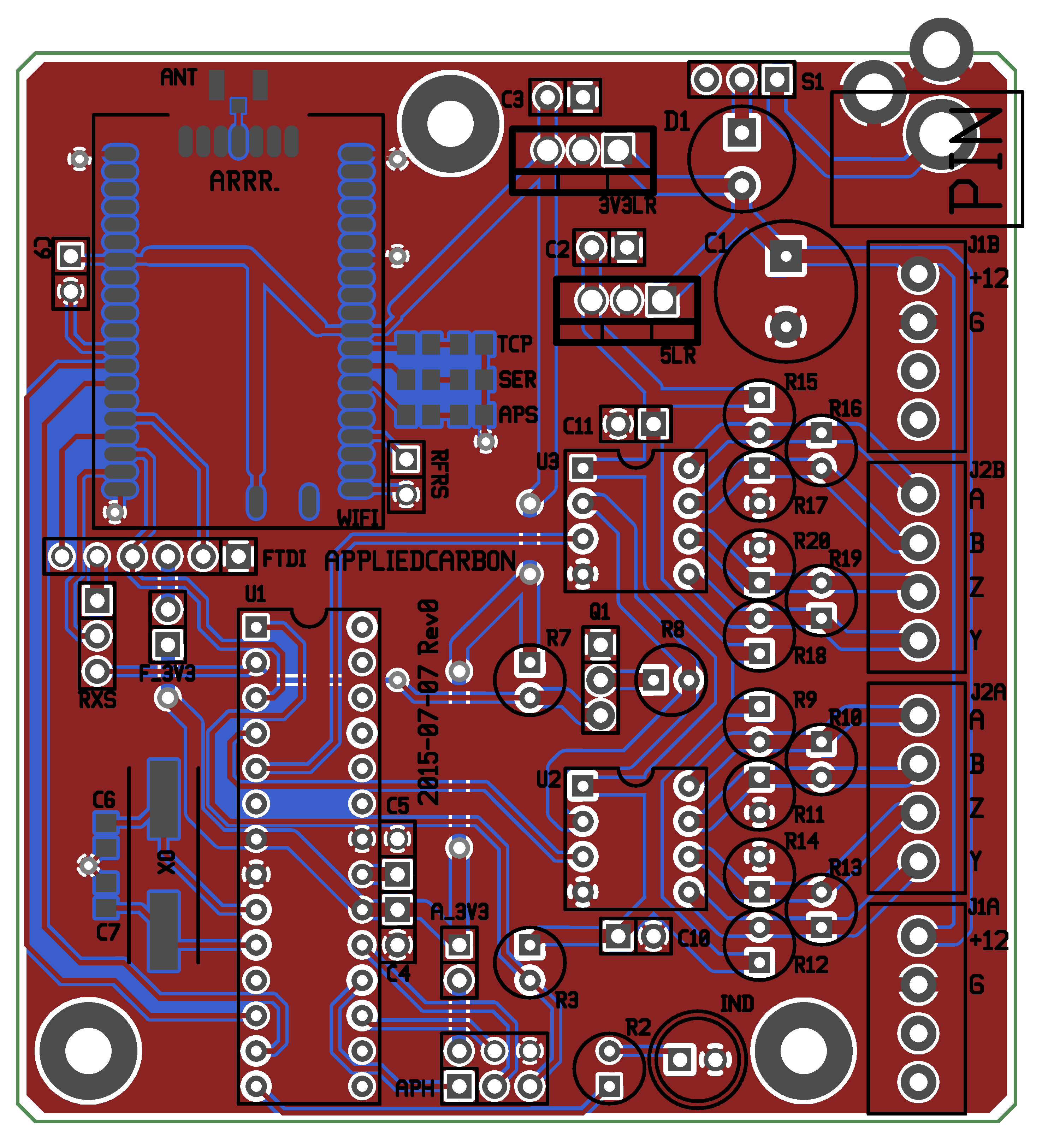
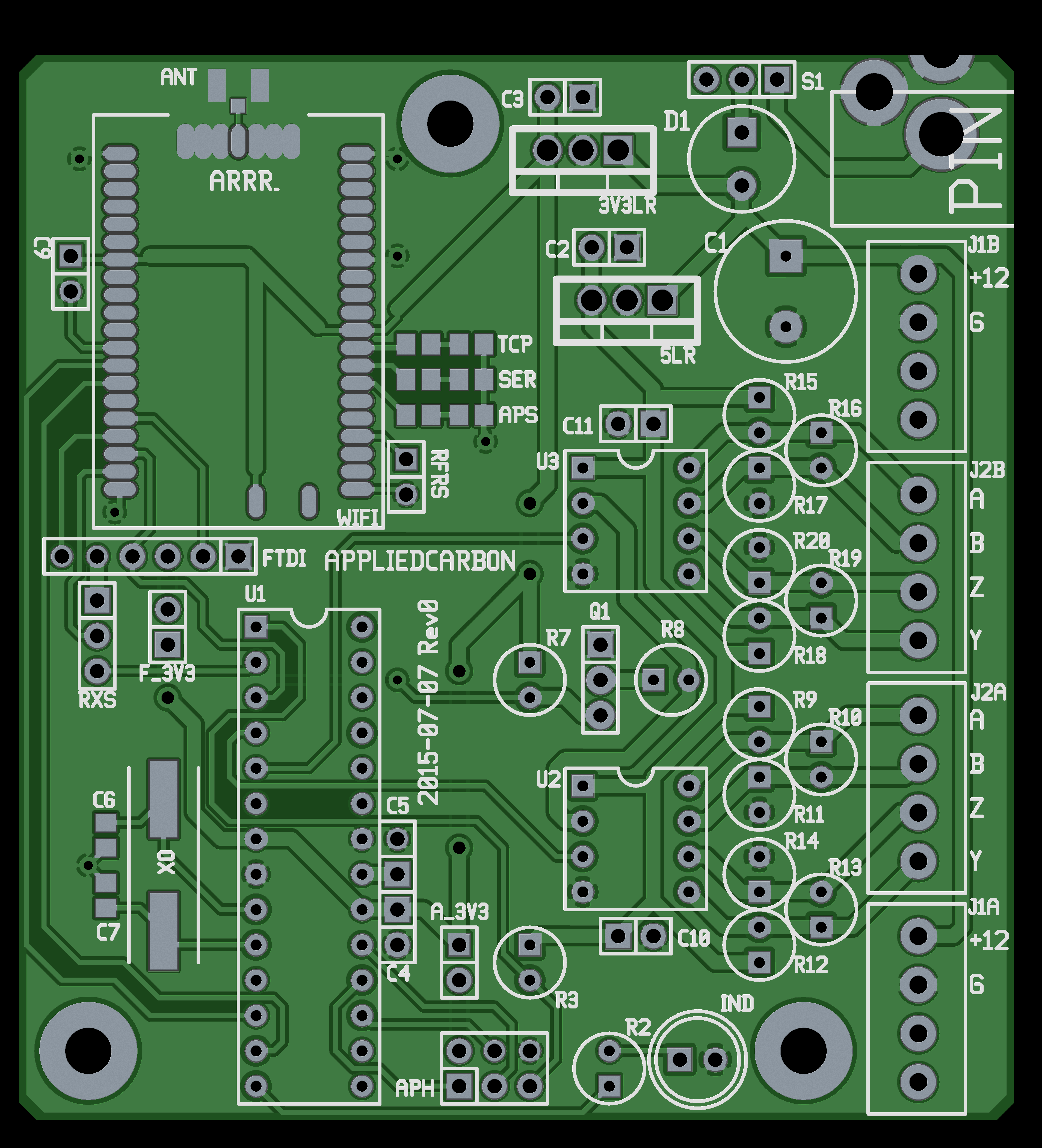
Schematics & Layout
Base-station board:Schematics: PDF
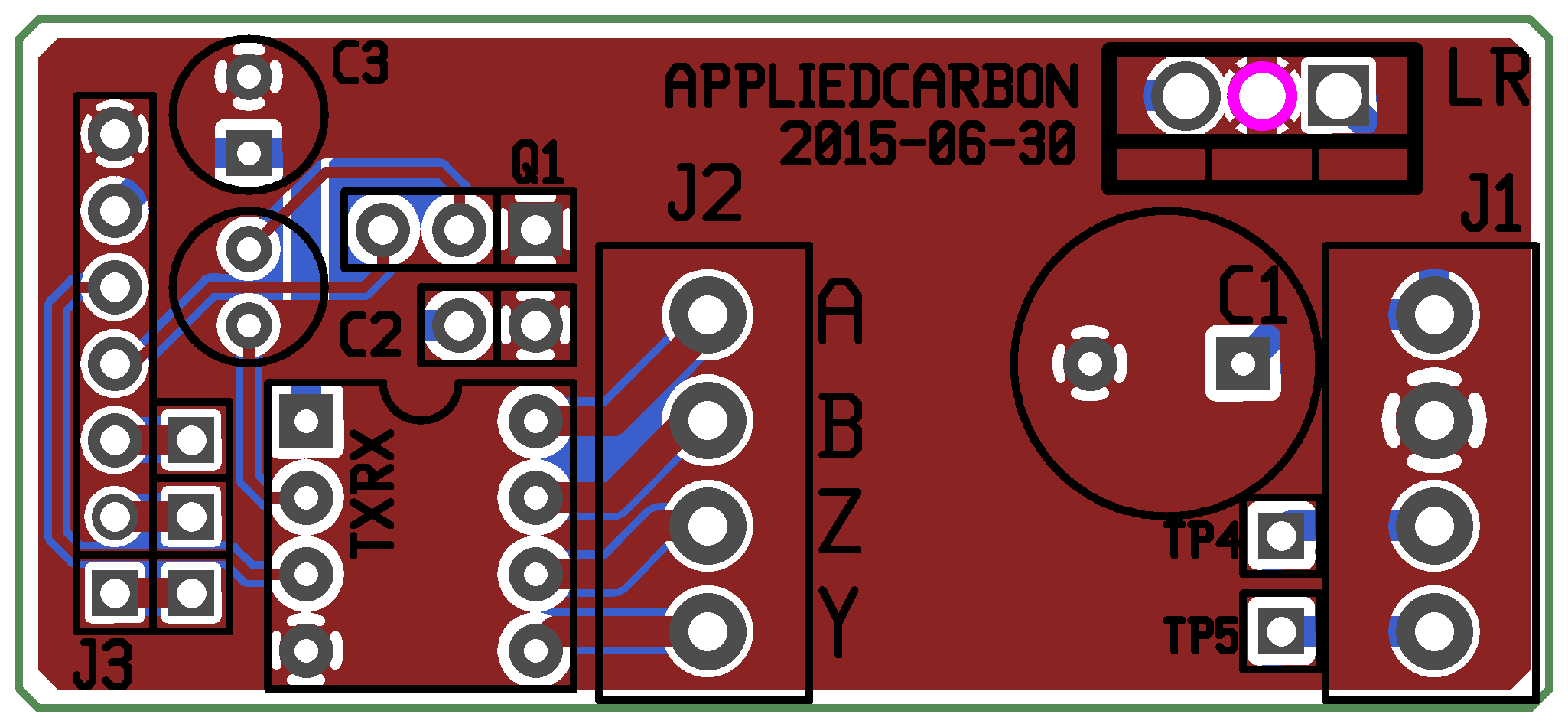
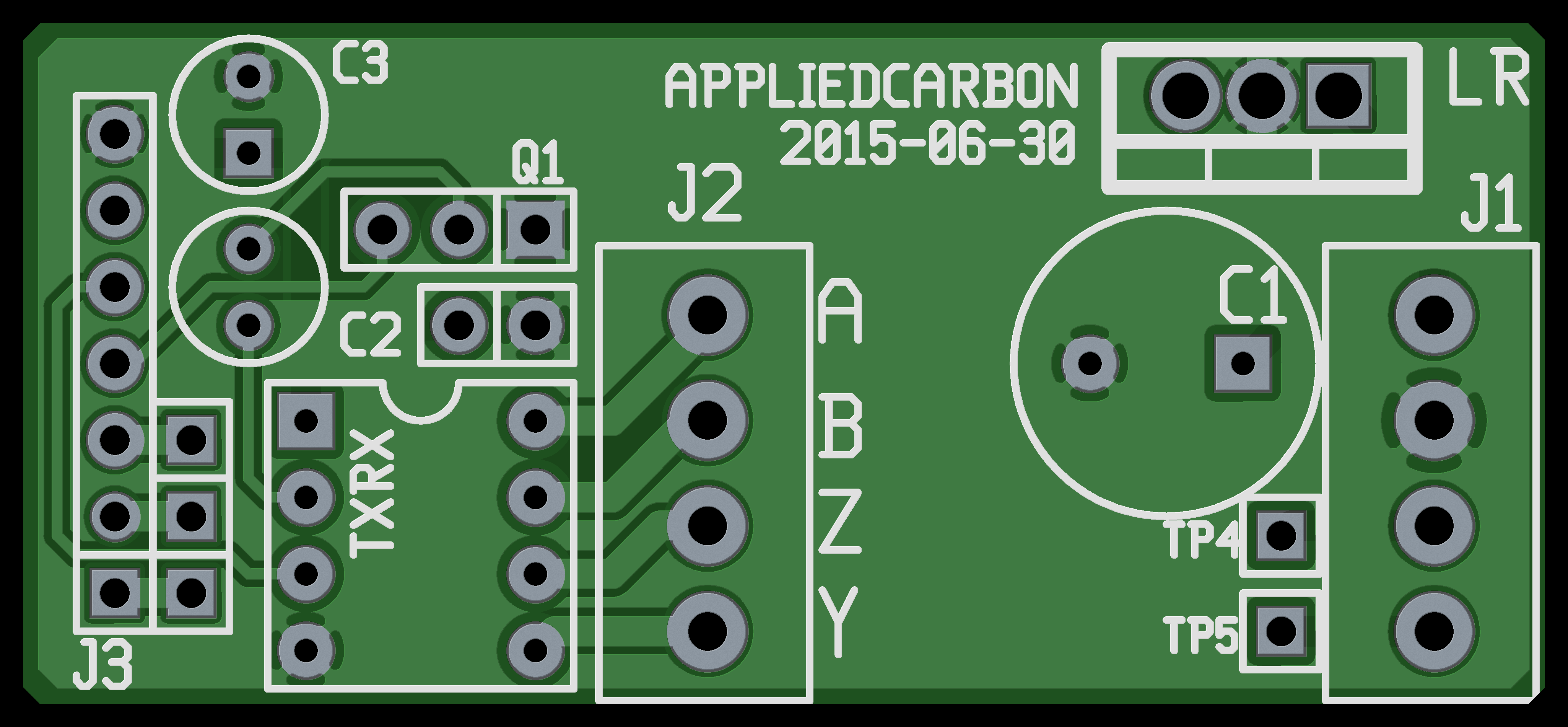
 Sensor interface board:
Schematics: PDF
Functional Description
The system is comprised of remote sensors, a "basestation" with WiFi connectivity and the control software, and a differential signal line from the basestation to each of the sensors.In the initial installation, only one sensor is installed. The sensor selection was fairly straightforward. The initial idea was to use a pressure transducer at the bottom of the tank: as the water level changed, the pressure would change. However, the tanks are only about 15 feet tall and the calculated pressure difference between a full and empty tank was too small to give a useful result with the sensors I had access to. The transducers were also in the hundred of dollars range which didn't look good from a budget standpoint.
Another idea that was floated (groan) was using a magnetic float in a vertical tube attached to the outside of the tank, and an array of Hall effect sensors or reed switches. An advantage with the system was one could check the level of the tanks visually without needed to open them. However, finding a potable-water-rated magnetic float proved difficult, and the modification of the water system to include the external level pipe was undesirable.
Maxbotix makes and array of inexpensive sonar sensors for purposes such as tank or bin level monitoring, and the weather proofed XL-MaxSonar-WR1 seemed to fit the bill. I have concerns about condensations collecting on the sensor face and it's performance in freezing temperatures, but it hit the right price point and was easy to installed. A bonus was that the sensor contains all the electronics and algorithms to do the distance calculation: when wired correctly it outputs RS-232 serial data with the detected distance. Extremely easy to use. The data from the sensor needed to be transferred through several hundred feet of forest. The simplest and cheapest way I could think of was to use a differential signal connection, derived from the RS-485 standard, run through a length of CAT5 cable down into range of the WiFi access point. I had a stack of TI SN75179B differential transceivers left over from a previous project, and they proved to be perfect. They're full duplex devices, meaning the receivers and transmitters use different wire pairs. One pair was used to transmit serial data from the remote sensor to the basestation, while the other was used to send a "take a reading now" signal from the basesation to the sensor. Another pair was used for power/ground, and the last pair is unused. The base-station used the ATMega168 to periodically get readings from the sensors. Approximately once a minute it sends out a signal to each sensor in turn. Since the microcontroller has a single UART pin, the RS-232 signals are wire-ORed (hence the need for the microcontroller to specifically trigger a read operation from each sensor), and the resulting output is inverted (converting the RS-232 signal to a form the UART could read) and voltage shifted with a transistor. The microcontroller trims some uneeded characters from the ultrasound sensor output and then writes three digits and a carriage return character to the RN-171 WiFi module.
Admittedly the ATMega168 is overkill for this application but it was what I had in my parts box and I am familiar with it. If this project was in mass production I would use something smaller and cheaper, such as the ATtiny2313.
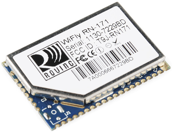
Photo courtesy of Sparkfun Electronics The RN-171 does the heavy lifting of this project. If I'm not mistaken it's running a variant of the LEON processor core and a Unix-like Real-Time Operating System. It has many, many options and I encourage new users to thoroughly read the datasheet and user manual. In this case, I used a feature that allows me to preset the website address and page URL, and then append whatever data I send the module to that address. Check out section 4.4.8 - HTML Client Example: Posting UART Data to a Web server on page 82 of the user manual for more information.
Here are my notes on the commands I used to setup the module:
Get into command mode: Press enter a bunch of times type '$$$' (no enter required after) Reset to factory default: factory RESETThe last element of the project is the website. In this case the client wanted a custom website with some specific graphs. The underlying system is built on PHP and a SQLite3 database. As configured, the RN-171 provides the data in the URL and the receiving webpage loads the measurement into the database.Set SSID of wireless network: set wlan ssid [your SSID here] Set WPA2-PSK auth mode: set wlan auth 4 Set the passphrase for WPA and WPA2 security mode: set wlan phrase [passphrase here] set ip proto 0x12 // Turn on HTTP mode = 0x10 and TCP mode = 0x2 set dns name sample.com // Set the web server name set ip host 0 // Turn on DNS set ip remote 80 // Set the web server port, 80 is standard set com remote GET$/getdata.php?data= // Set up the server application string set option format 1 // Send a HTML header set uart mode 0x02 // Make TCP connection upon UART RX data Tell the module to send the UART data it received if it hasn't received more data for three seconds: set comm time 3000 Save the settings and reboot: save reboot
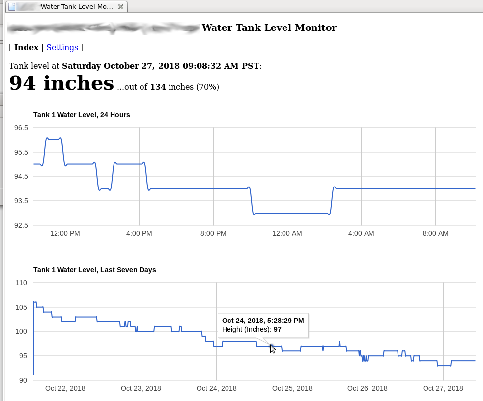
Not going to win any design awards, but it gets the point across.
Bugs, Errors, Lessons Learned (Added 2018-10-27)
Probably the biggest lesson from this project was to slow the heck down.For various reasons I was under a significant amount of pressure to get this designed, built, and installed ASAP. One thing I had be doing in previous projects (when time wasn't a factor) was stepping away from the project for a few days, when I thought it was done. When I came back and took a fresh look at it I always found something I had missed previous: innocuous as bad labels or as serious as an under-specced part in the design. In this case (in the interest of time) I went from my notes to a PCB layout to the fab house immediately, and ended up with some basic errors: The pinout of the RXS jumper on the base station board was wrong. The U.FL footprint wasn't thermally isolated from the ground plane, made it very difficult to solder. Somehow the power jack pins ended up not matching the silkscreen outline. I forgot to add the termination resistors to the sensor interface board (soldered them on the back). The 3.3 volt linear regulator footprint (3V3LR) pinout was wrong.
Thankfully nothing was so far off that the PCBs I ordered were unuseable; just needed some creative wiring to get everything working. I was very happy that the differential signaling worked out on the first try, exactly as I planned.
Obviously I had tested a short run in my shop, but doesn't mean I had thought of everything. A lab test and a field install are very different things. This system was installed in July of 2015. In September of 2018 I was informed by the owners that the system had failed in some way. A subsequent check-out showed that the RN-171 module had failed: for whatever reason it refused to connect to the webpage I had indicated, and no amount of factory resets would convince it to work. Given that the RN-171 was essentially EOL and cheaper options had come into being in the intervening years, I recommended building a new base-station board. Check out System 2 for the upgrade.