
Teardown of a TI-92 Plus
Last Update: Aug 12, 2021
Introduction
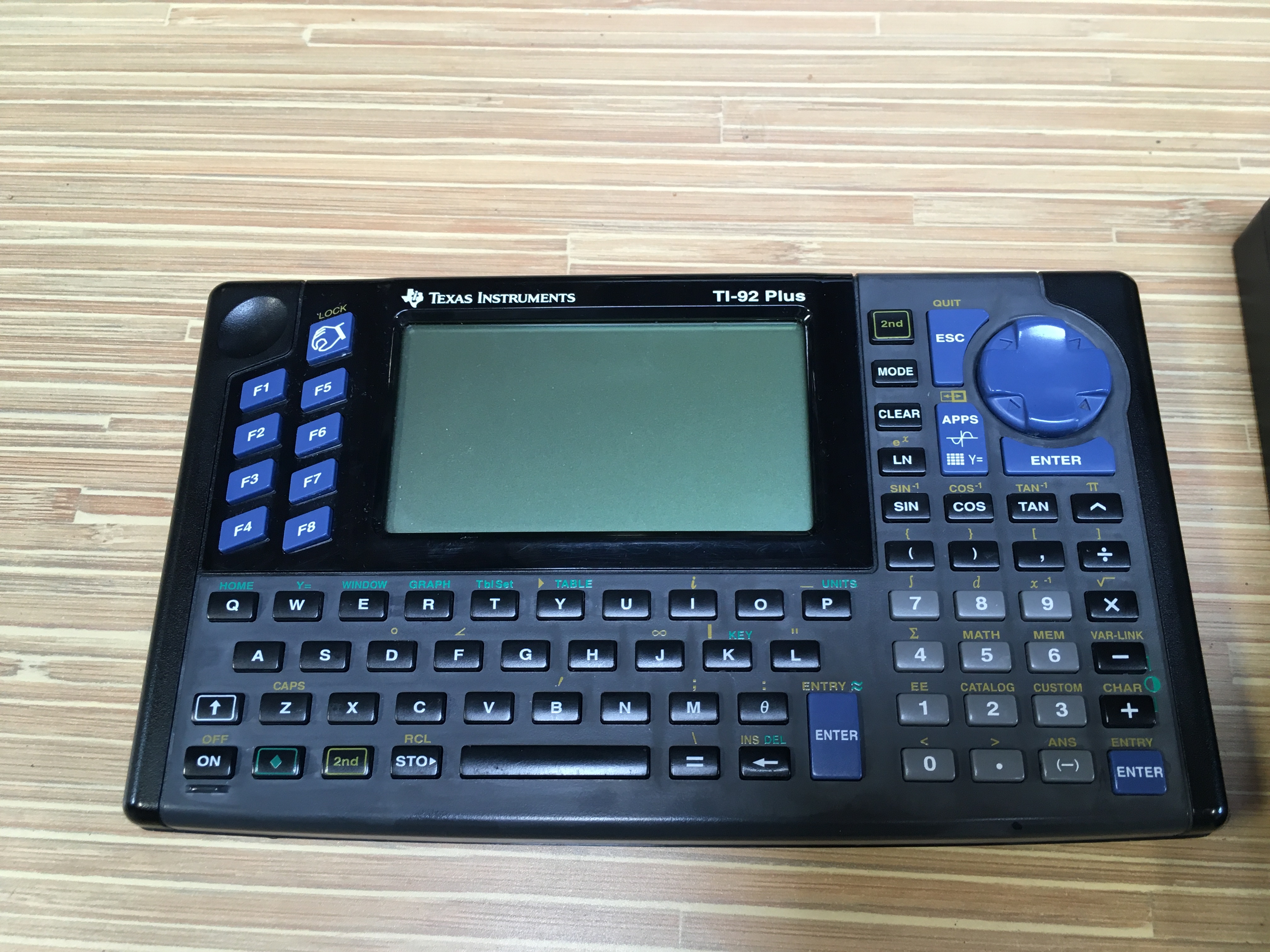
My day job involves Numbers. Lots of numbers, sometimes.Typically I use the calculator that is built into whatever OS I'm using, but apparently Windows Calc sends telemetry to Microsoft, and generally I'm interested in unhooking my life from the various always-connected all-in-one systems that fill our lives. One of the universal experiences in the US is the Texas Instruments calculator.
Virtually all school children have used one, and dropping fifty bucks on something that probably costs an order of magnatude less to actually manufacture is a right of passage into the world of higher level math. So, while looking for a desk calculator, I vaguely recalled a TI device with a full keyboard in addition to standard math functions. The rumor was (when I was a kid) that it had a fairly serious processor and could play DOOM.
 After a quick search on Wikipedia it turned out that none of that was true. That said, as a retro-computer hobbyist, having an oversized calculator from the 90's appealed to me.
A trip to eBay netted two for $20 each - looks like a lot of schools are liquidating their inventories?
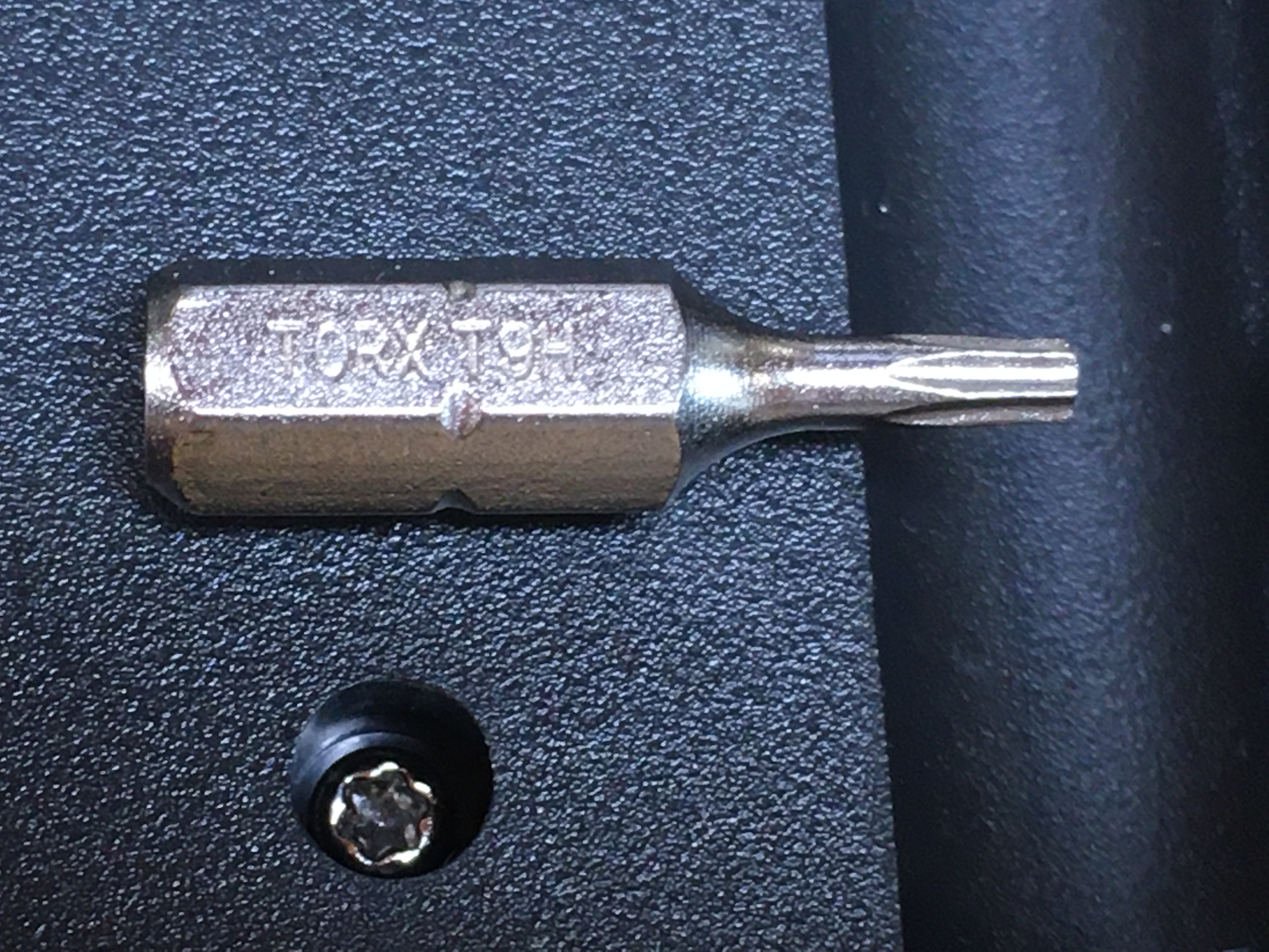
Open the Case
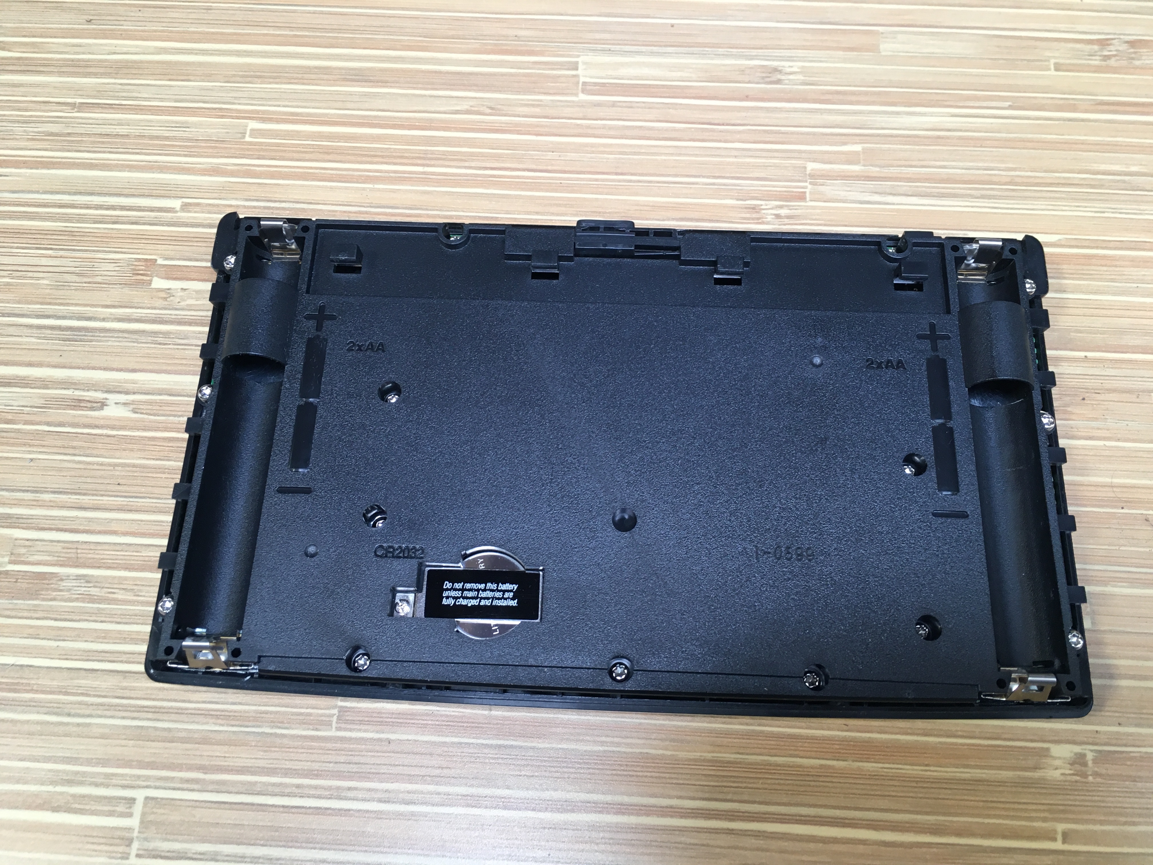
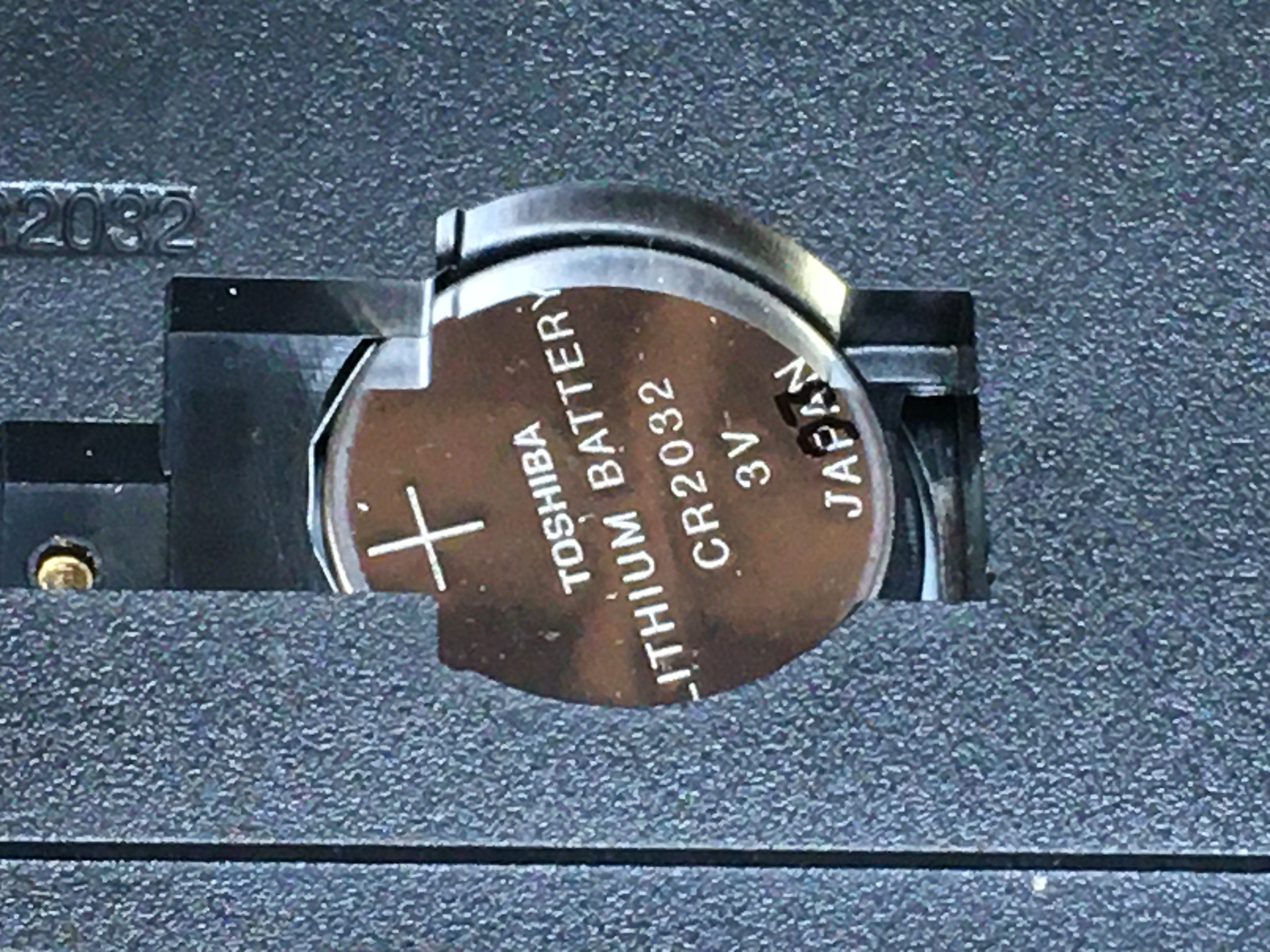
Opening up one of these calculators is straight-forward. All you need is a Phillips screwdriver and a size 9 Torx bit.The back pops off without tools, pull out the AA's and the CR2032 (memory backup) cell.
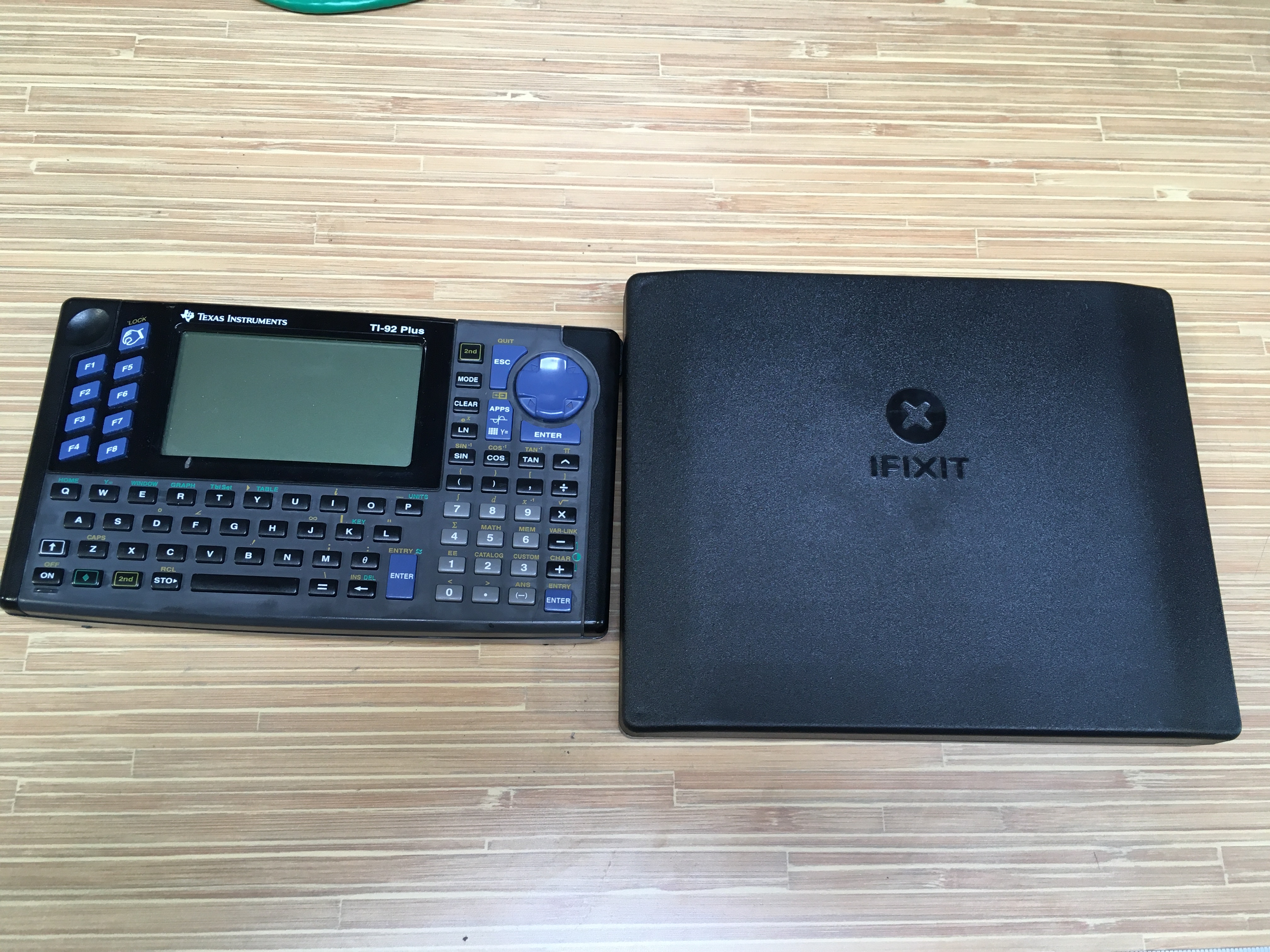
 Shout out to iFixIt and their Manta Driver tool kit. It's got just about every bit you'll ever need to open up consumer electronics.
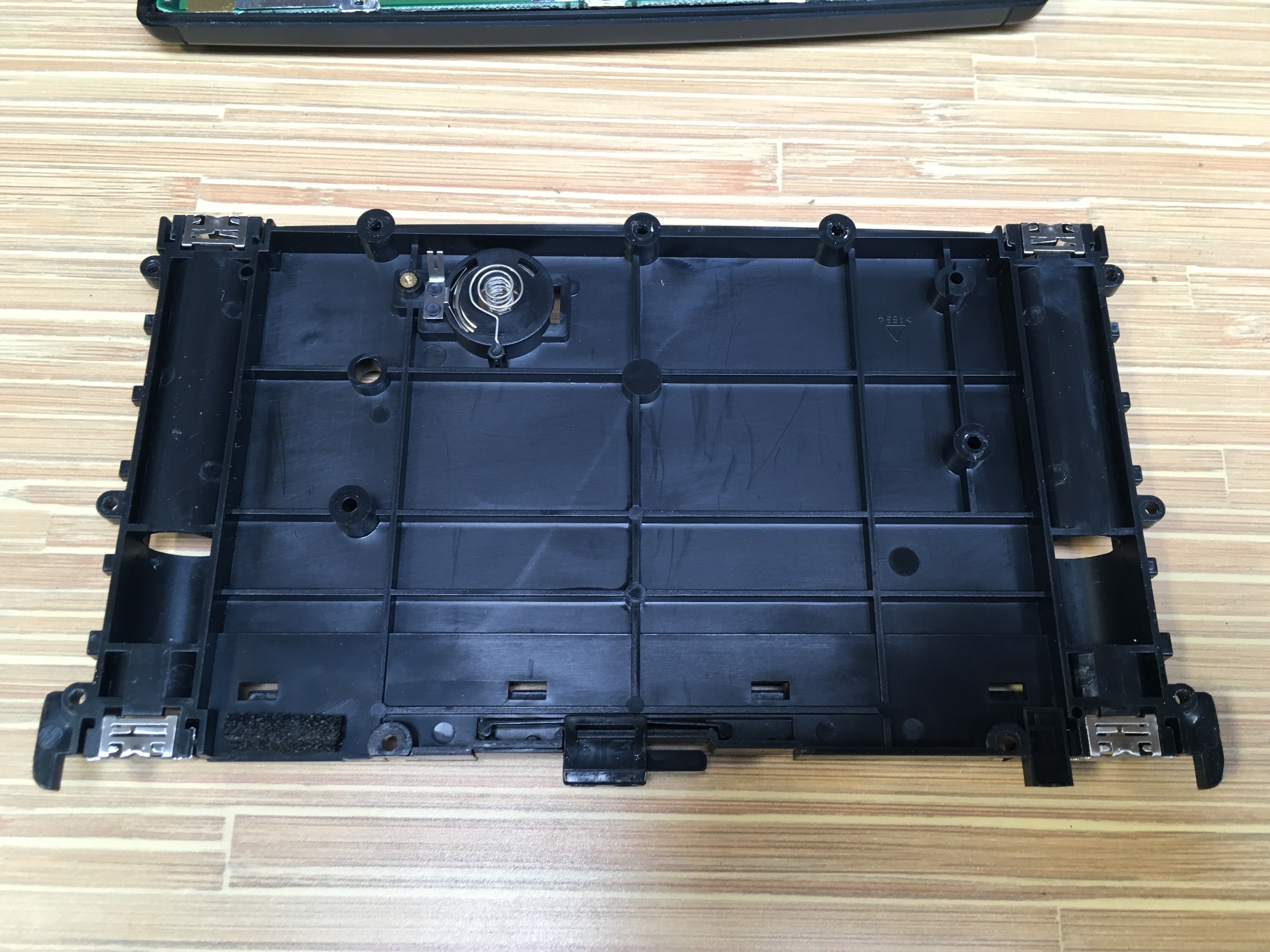
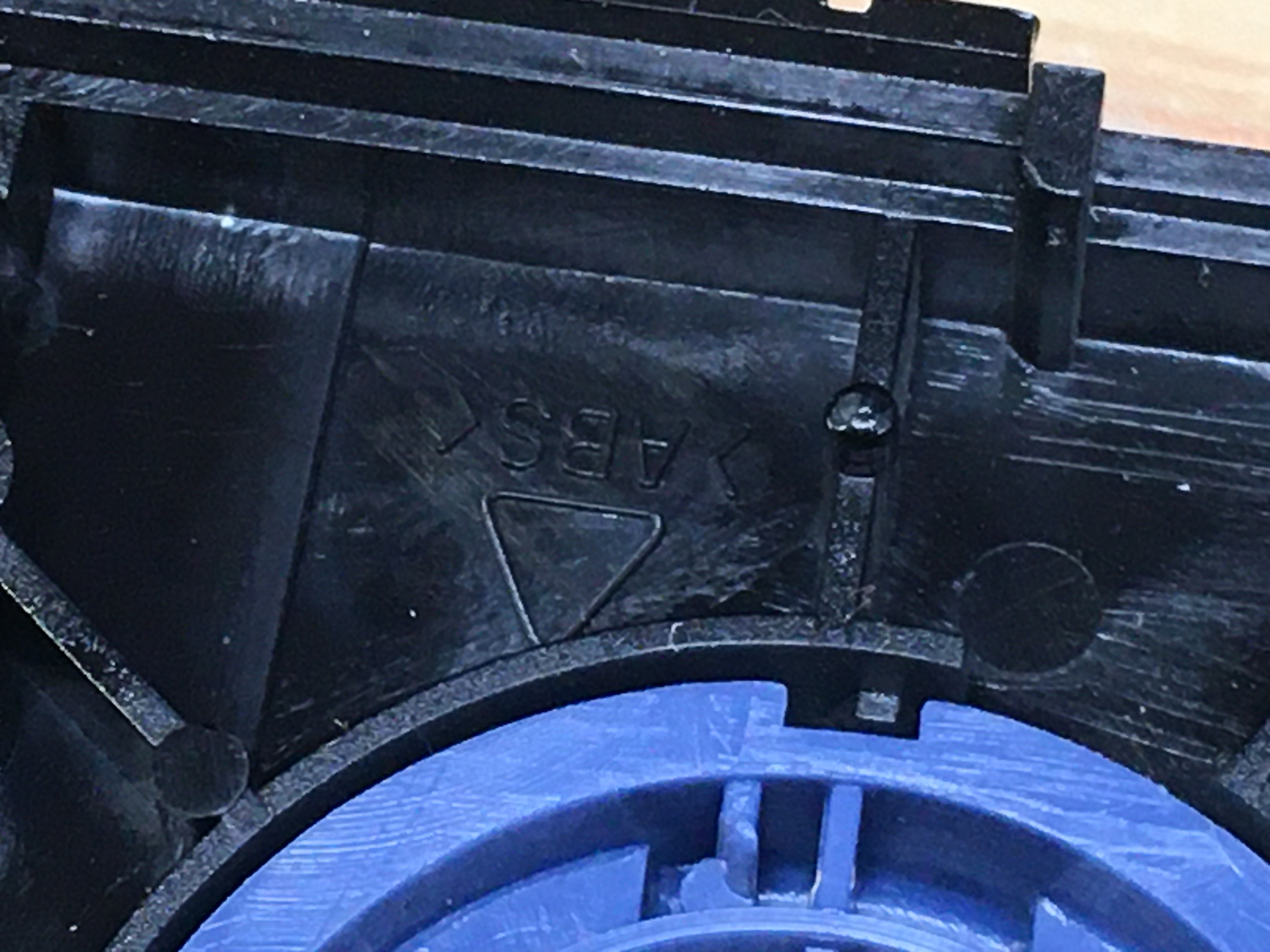
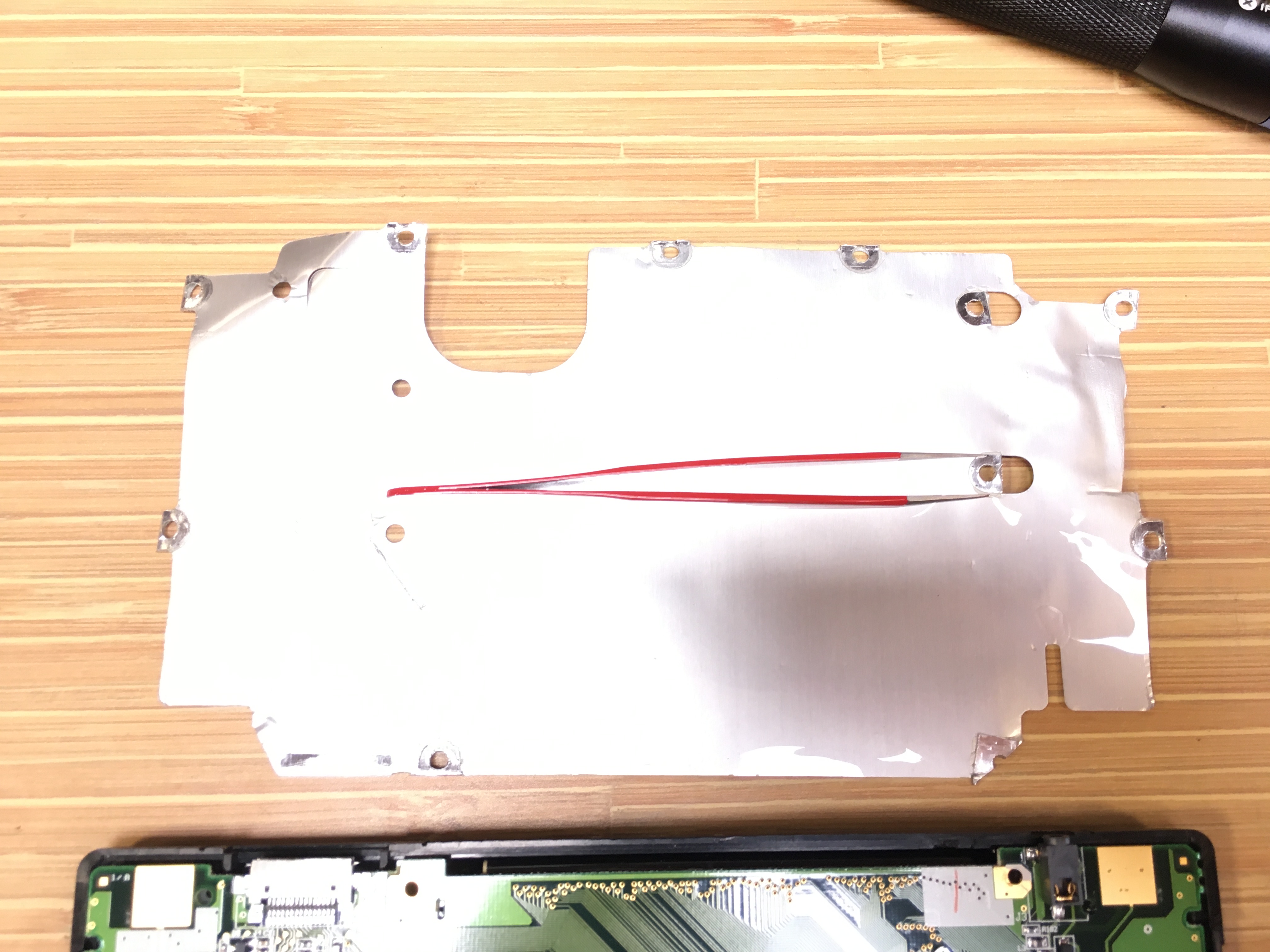
 The internal back panel is an injection molded ABS part, with a couple of press-in metal bits for the cells.
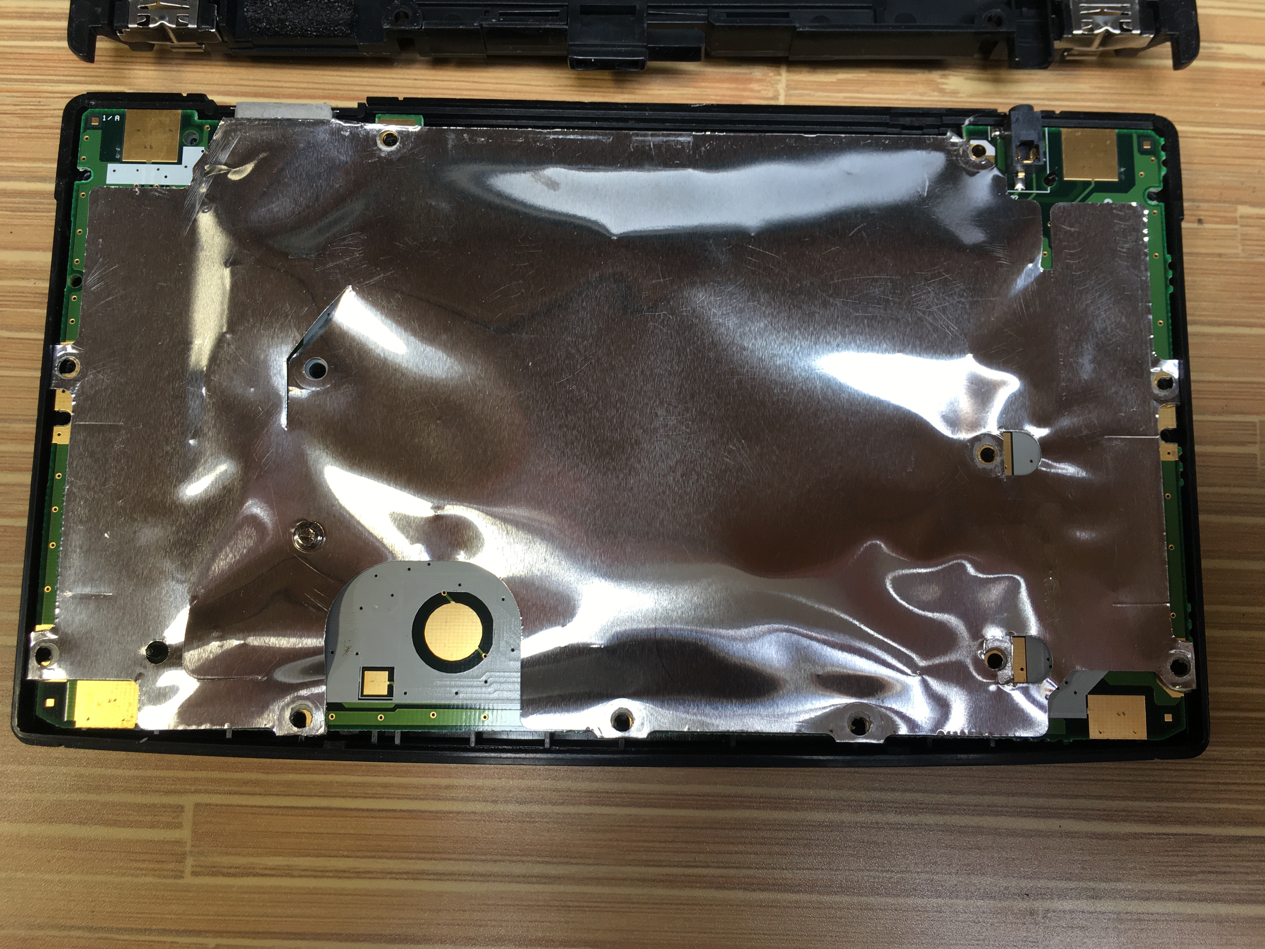
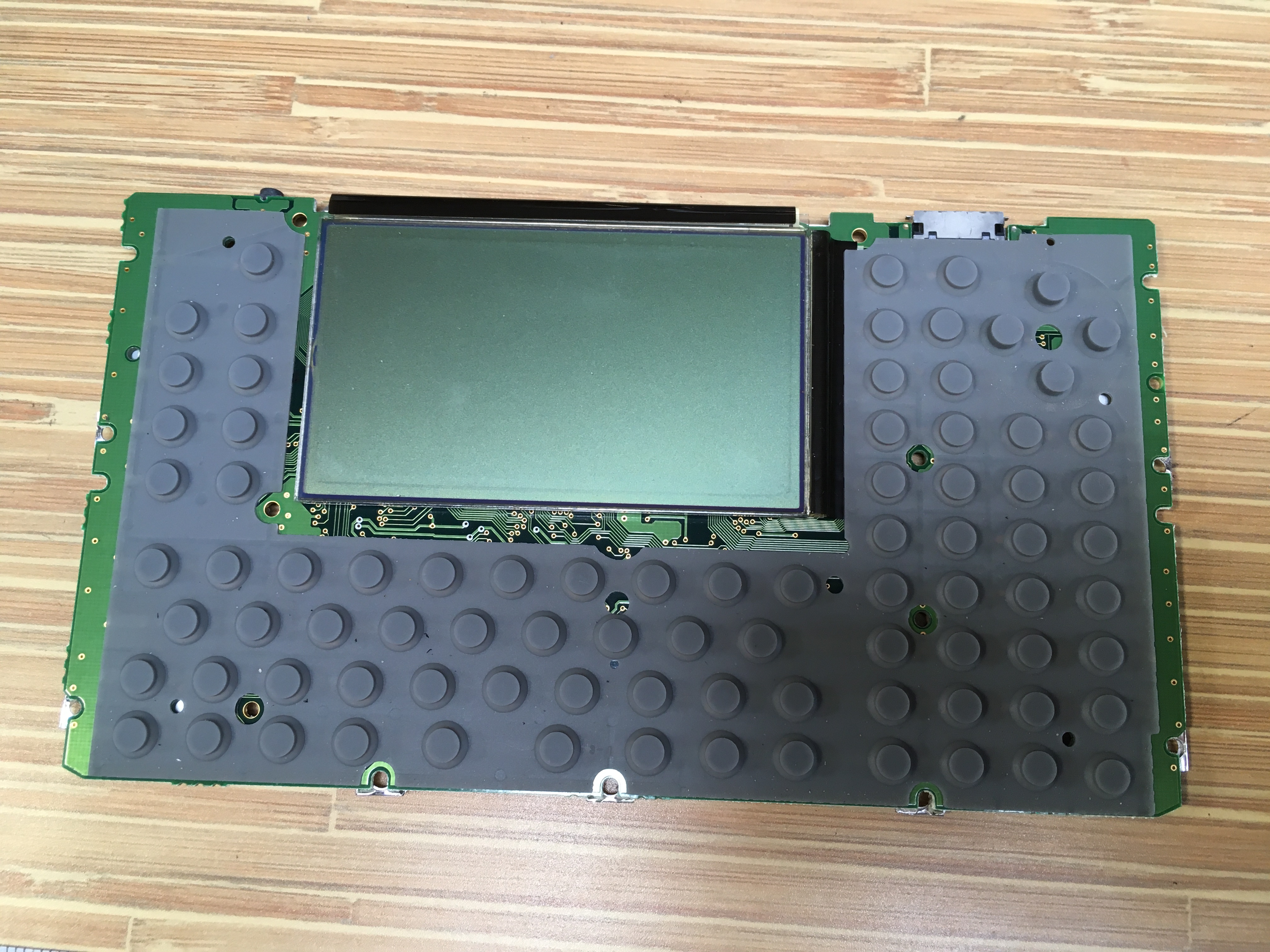
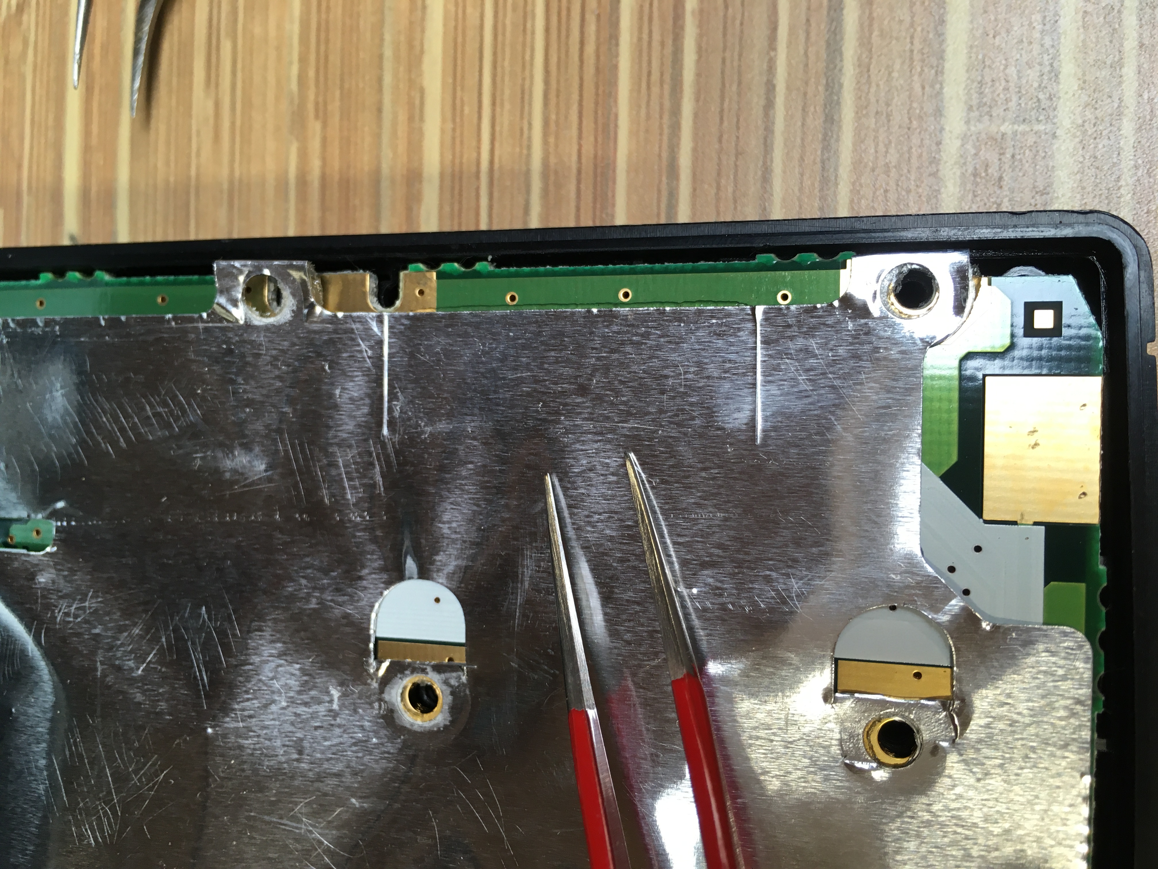
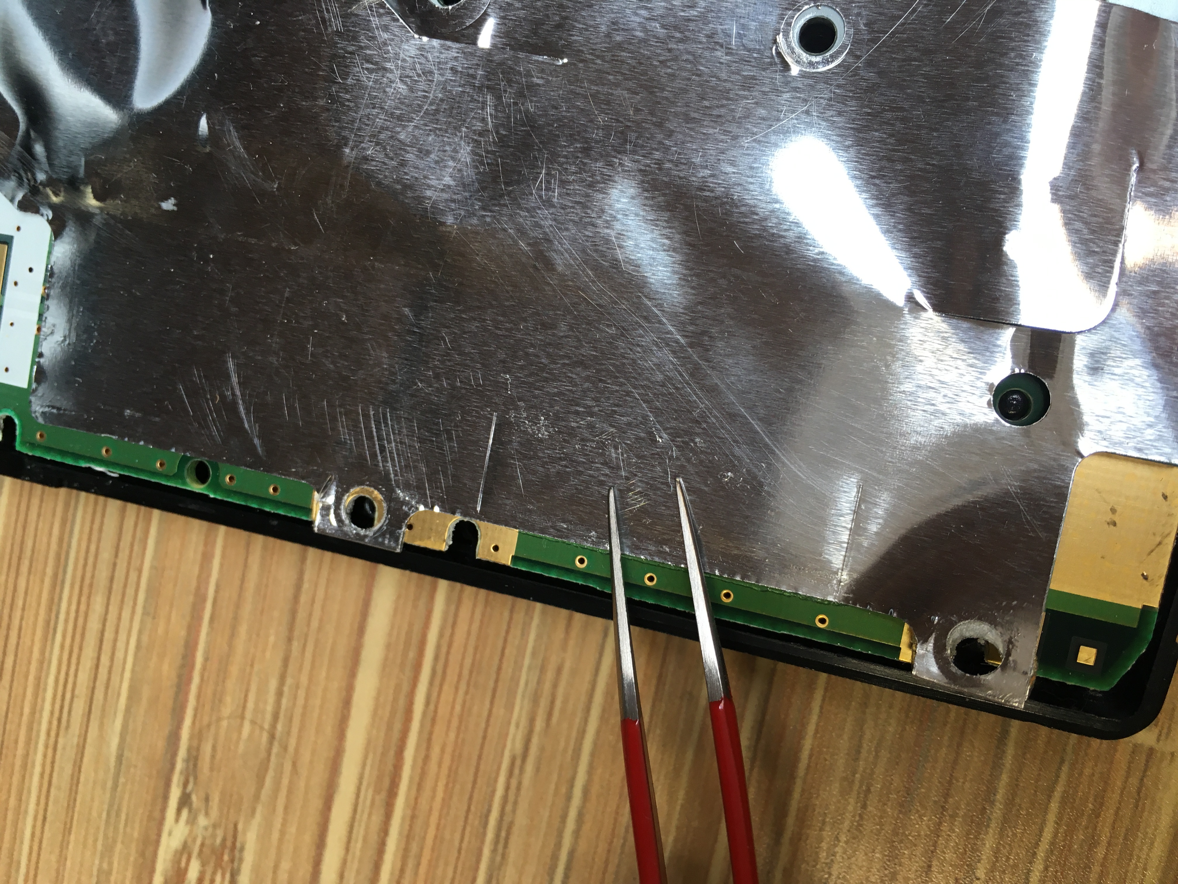
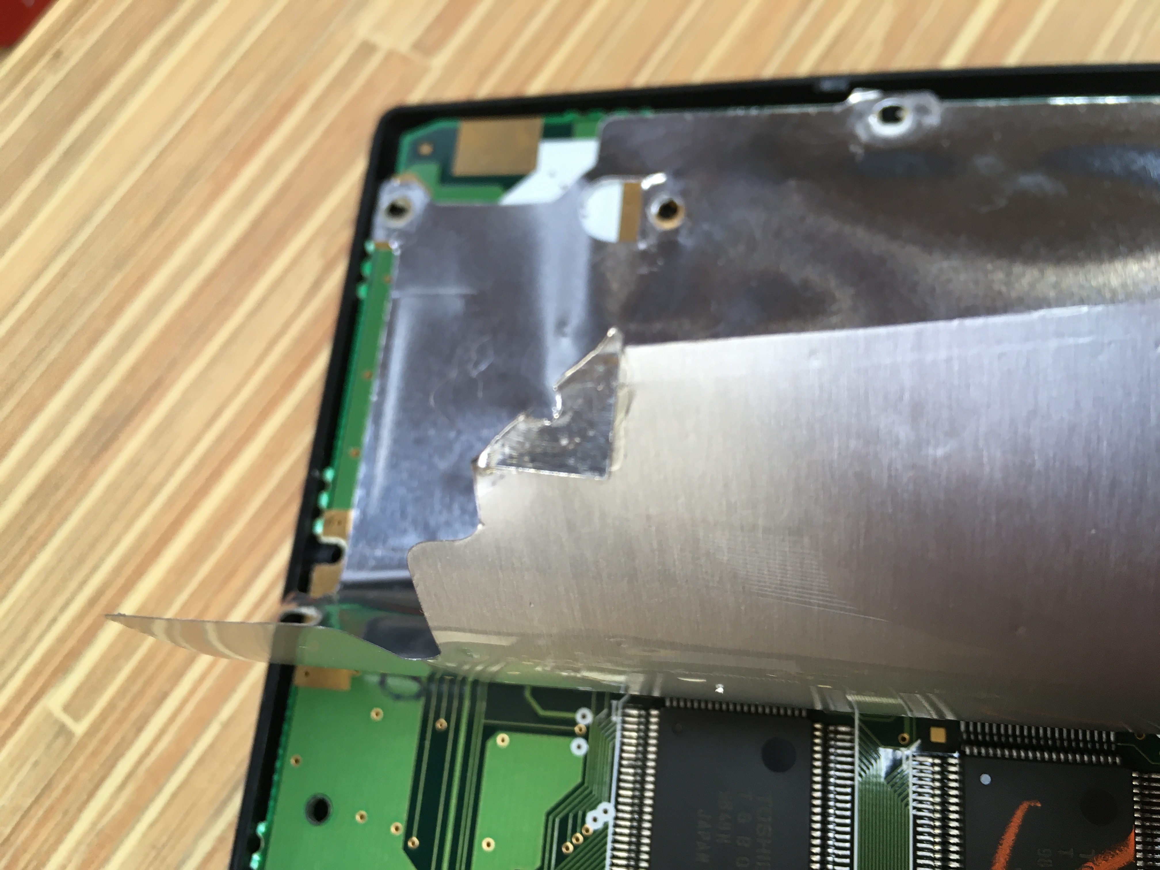
 The main PCB has a metal/plastic sheet glued on, presumably EMI/RF shielding.
Surprised to see this, honestly. I can't remember the last time I saw any kind of shielding in any consumer device - presumably due to cost pressures.
 A couple of screws hold the PCB to the front face plastic, after which it just lifts out. Typical membrane keyboard design.
Another tool shout-out: Electro-Optix/Vetus tweezer in the upper right. I think it's a No. 7 - came in useful six item set.
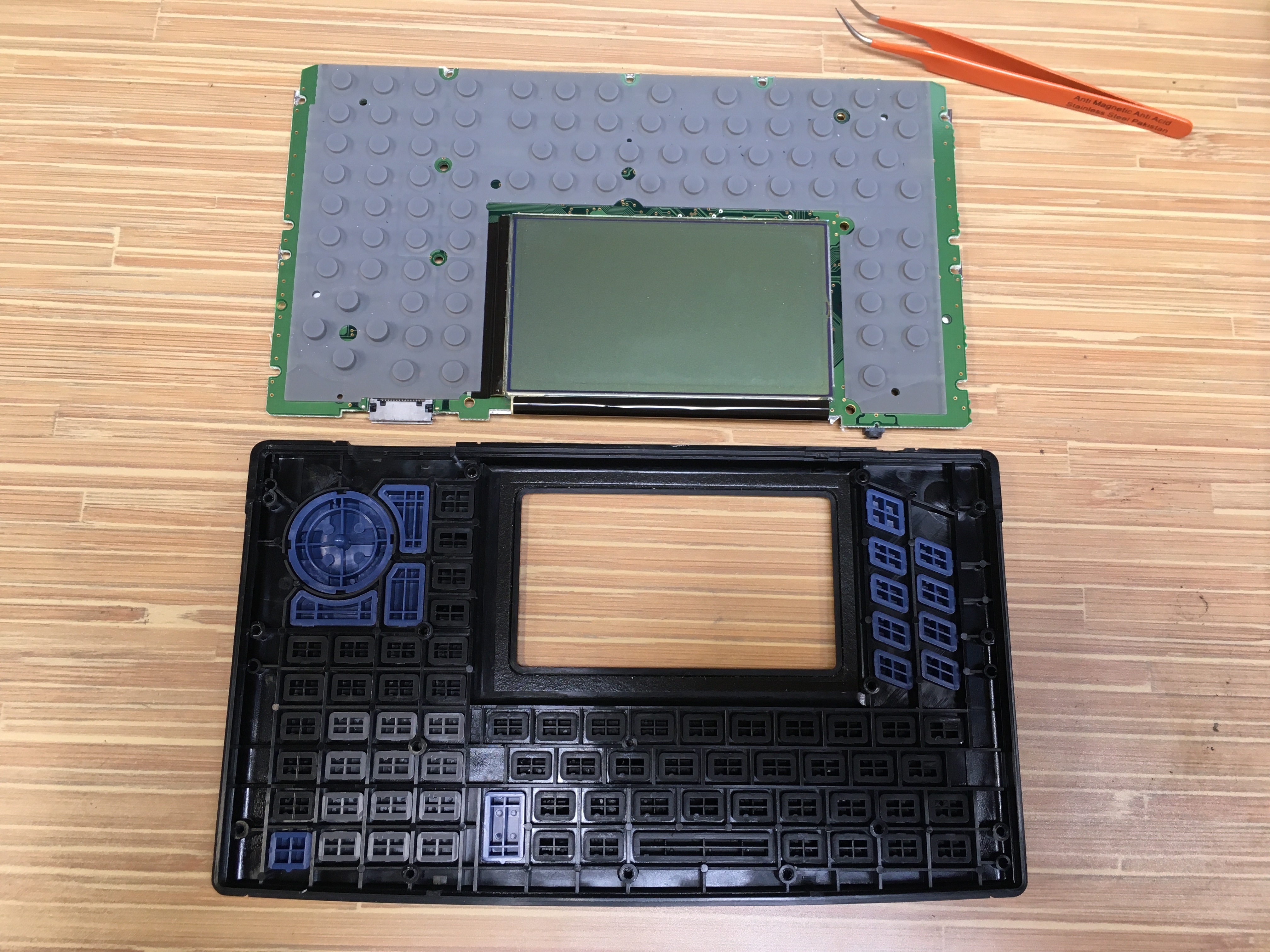
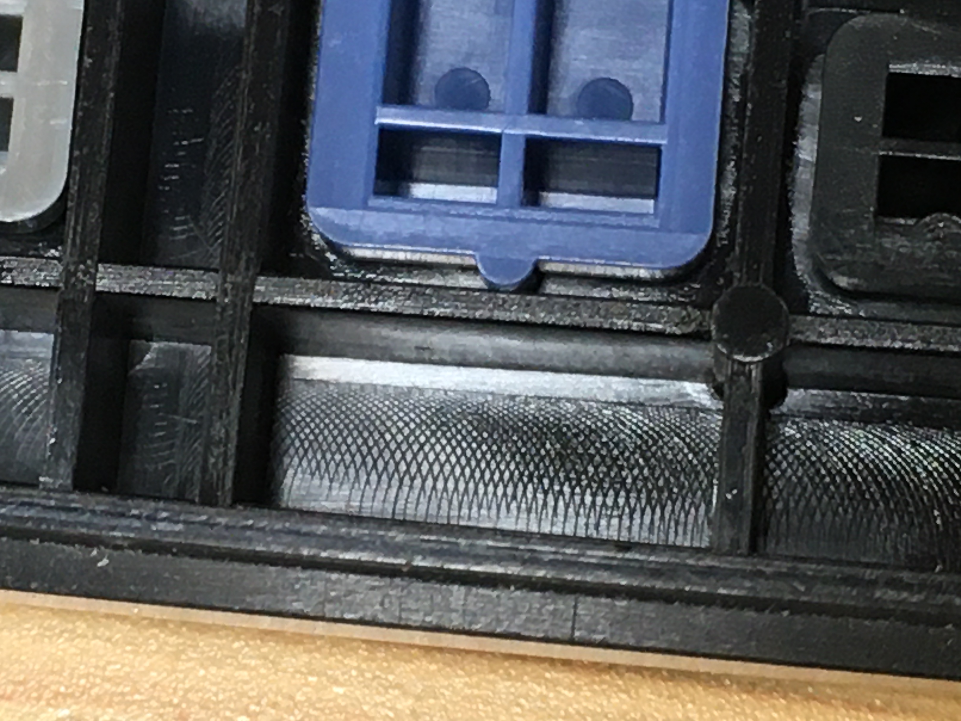
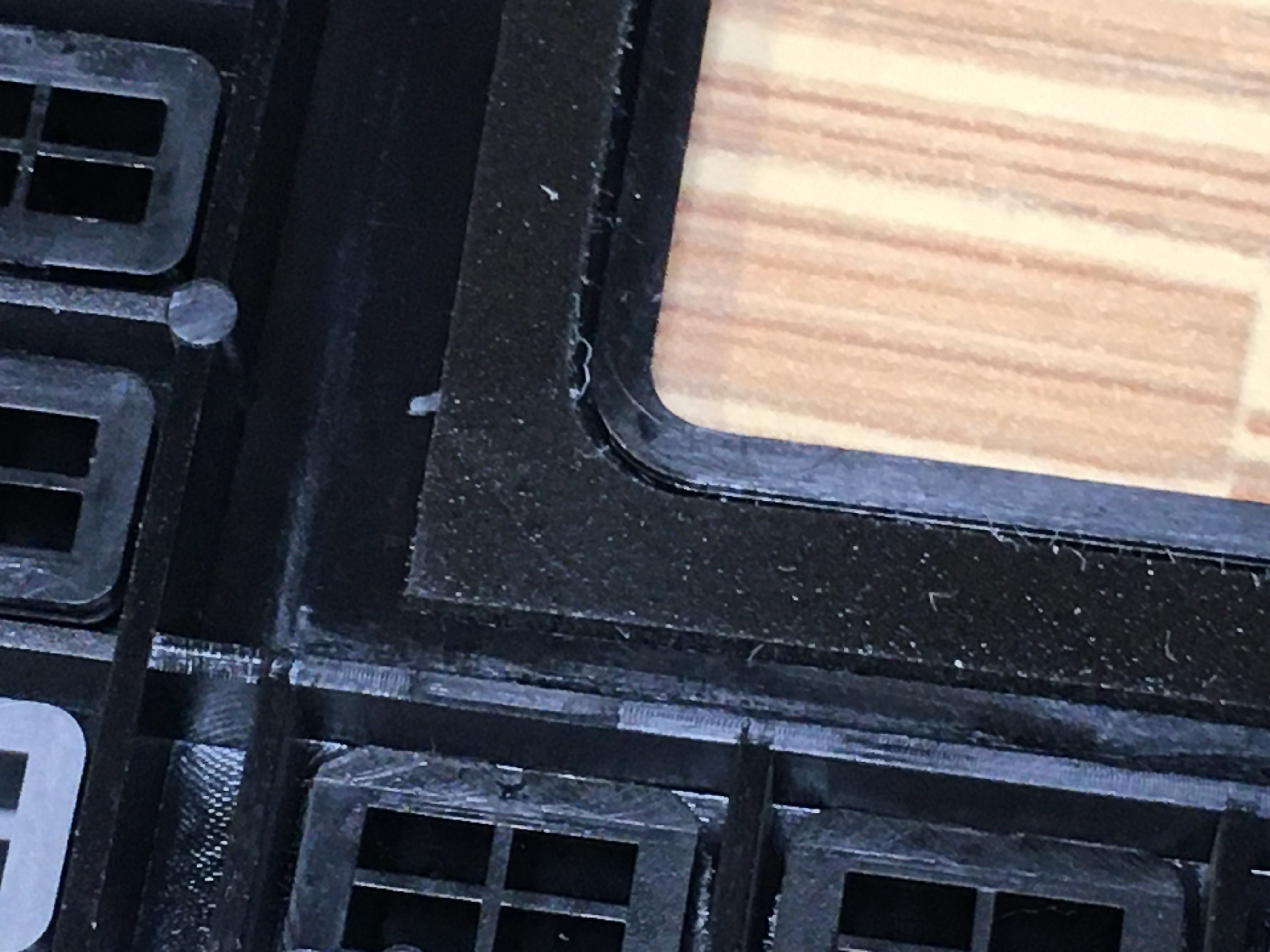
 A few detail shots of the front face part. Looks to be injection molded ABS, no surprise.
Note the padding around the display opening - neat detail, probably to keep debris out of the calculator case.
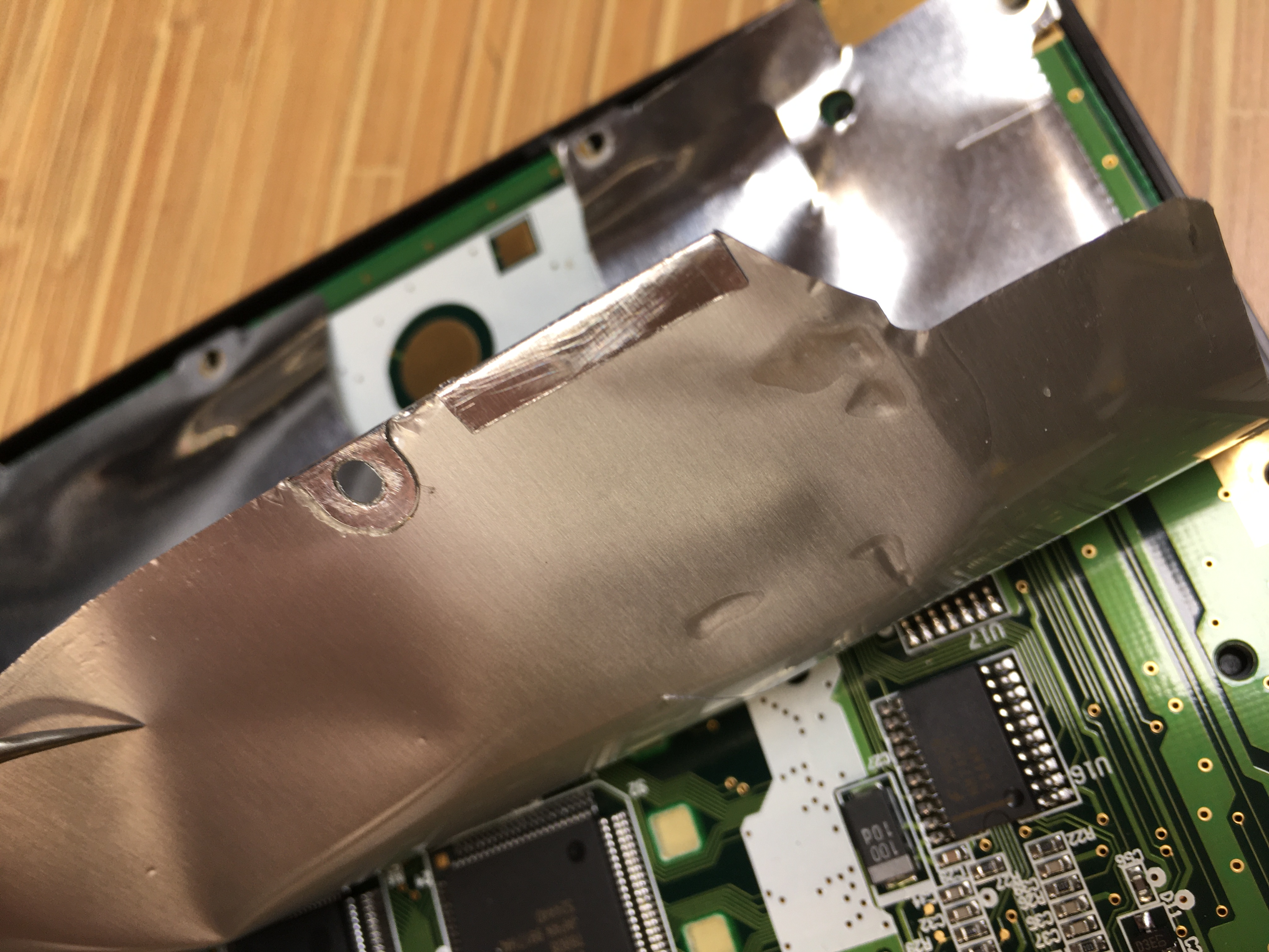
Shield
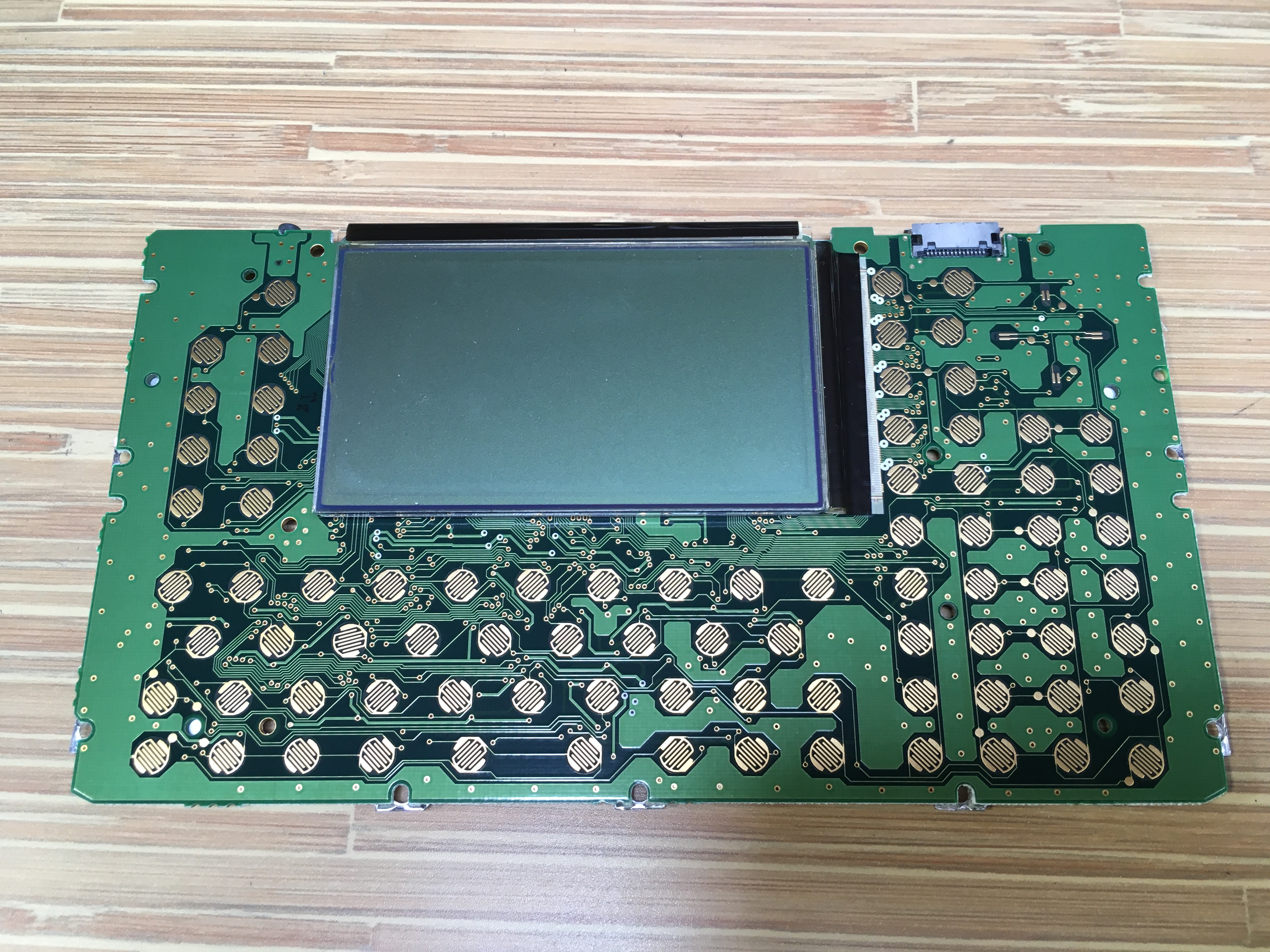
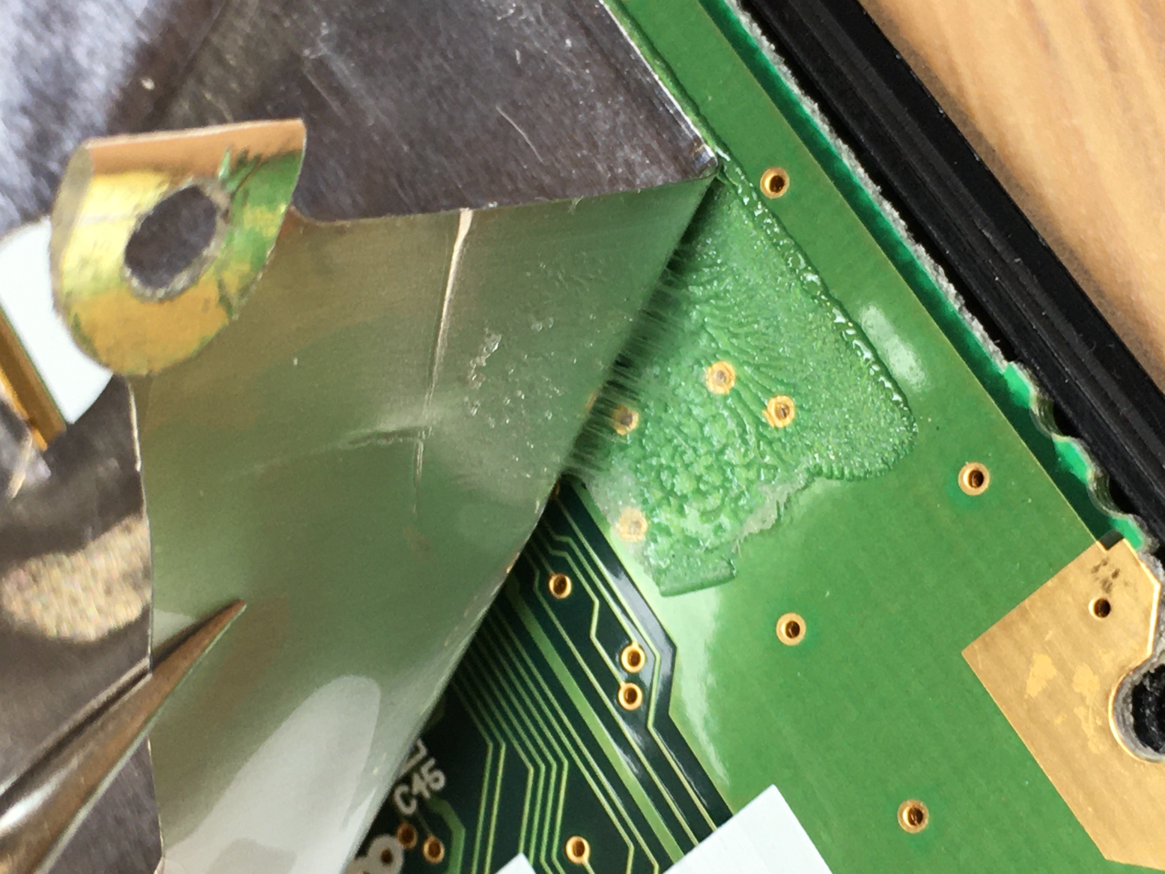
If you want to get at the electronics, you'll need to peel off the metalized plastic sheet.It's glued to the PCB in a couple of points, but the adhesive responds well to a gentle pull and heat gun on the lowest setting.
Printed Circuit Board (PCB)
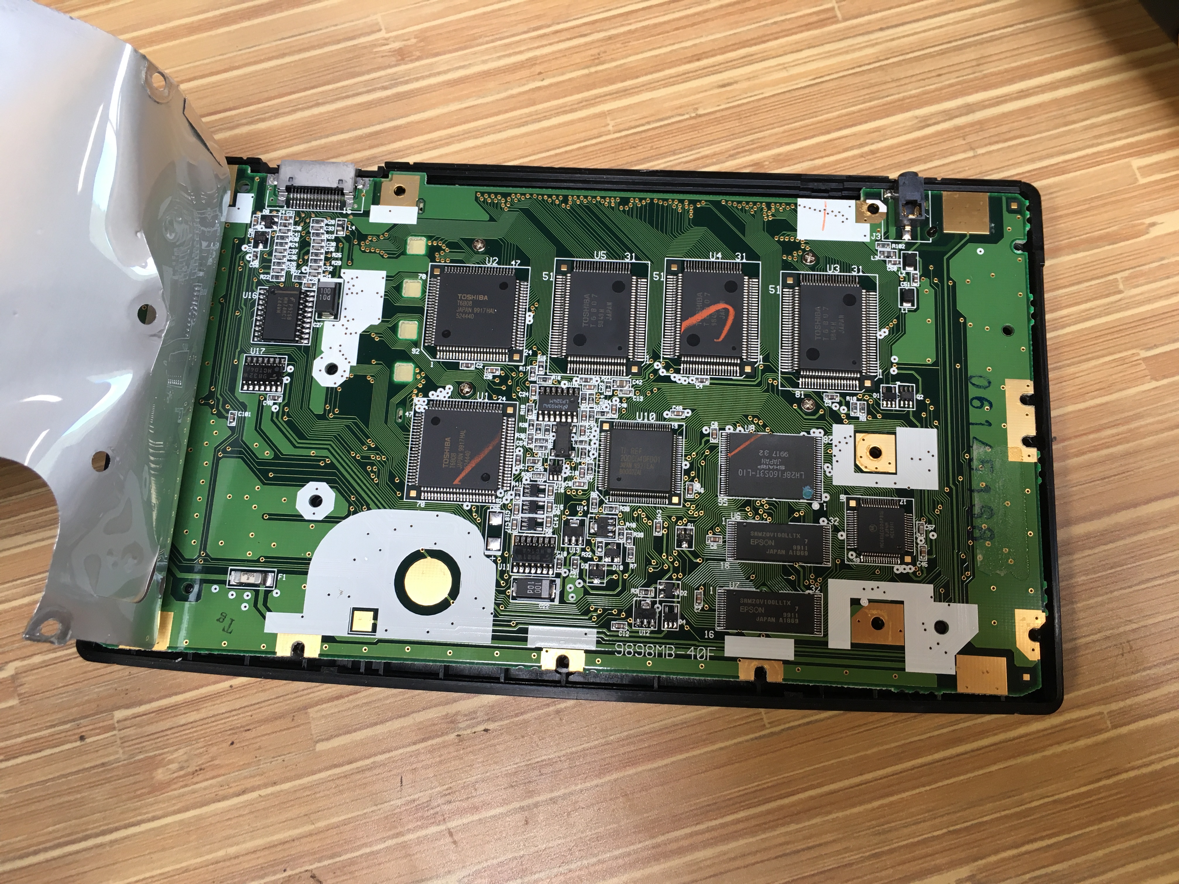
I put the PCB back in the front face plastic, and screwed it down to keep the buttons from falling out: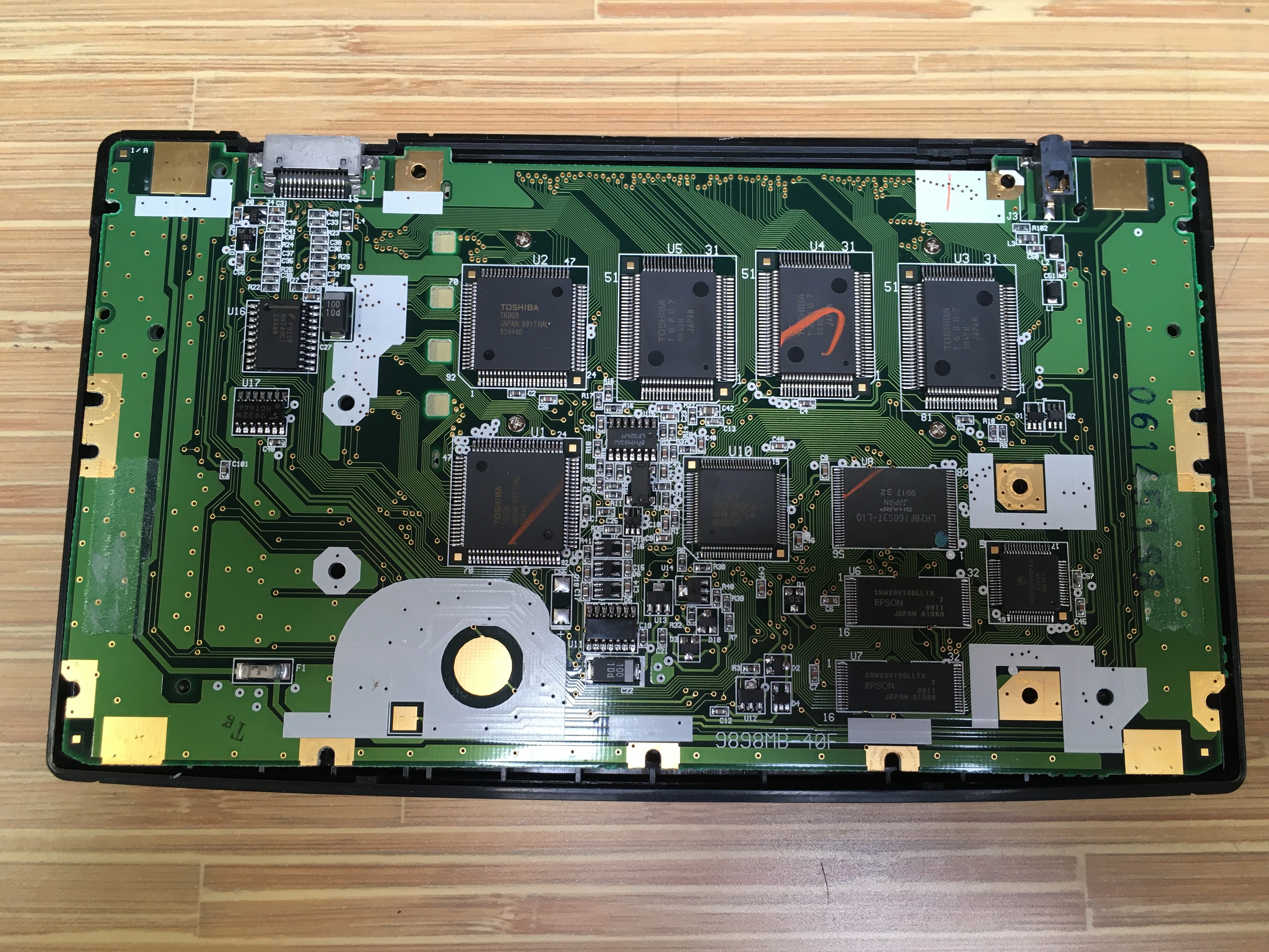 Silk screen part number:
 9898MB-40F.Black ink on PCB:
06145168 - serial number?There is also
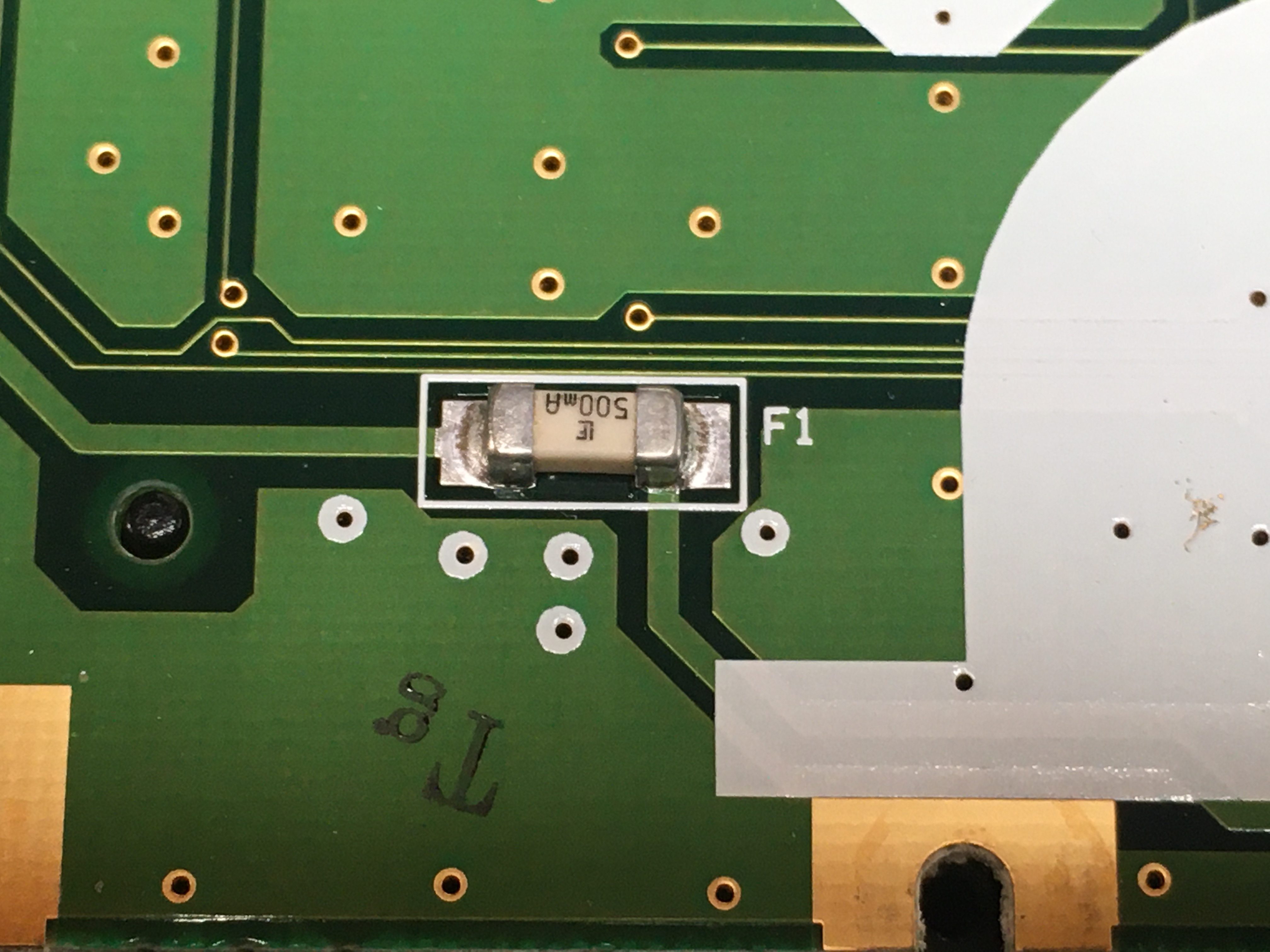
Tg in black ink near the fuse. Quality control station mark?
Orange ticks on some of the chip packages are probably QC sign-offs on parts after testing was performed.
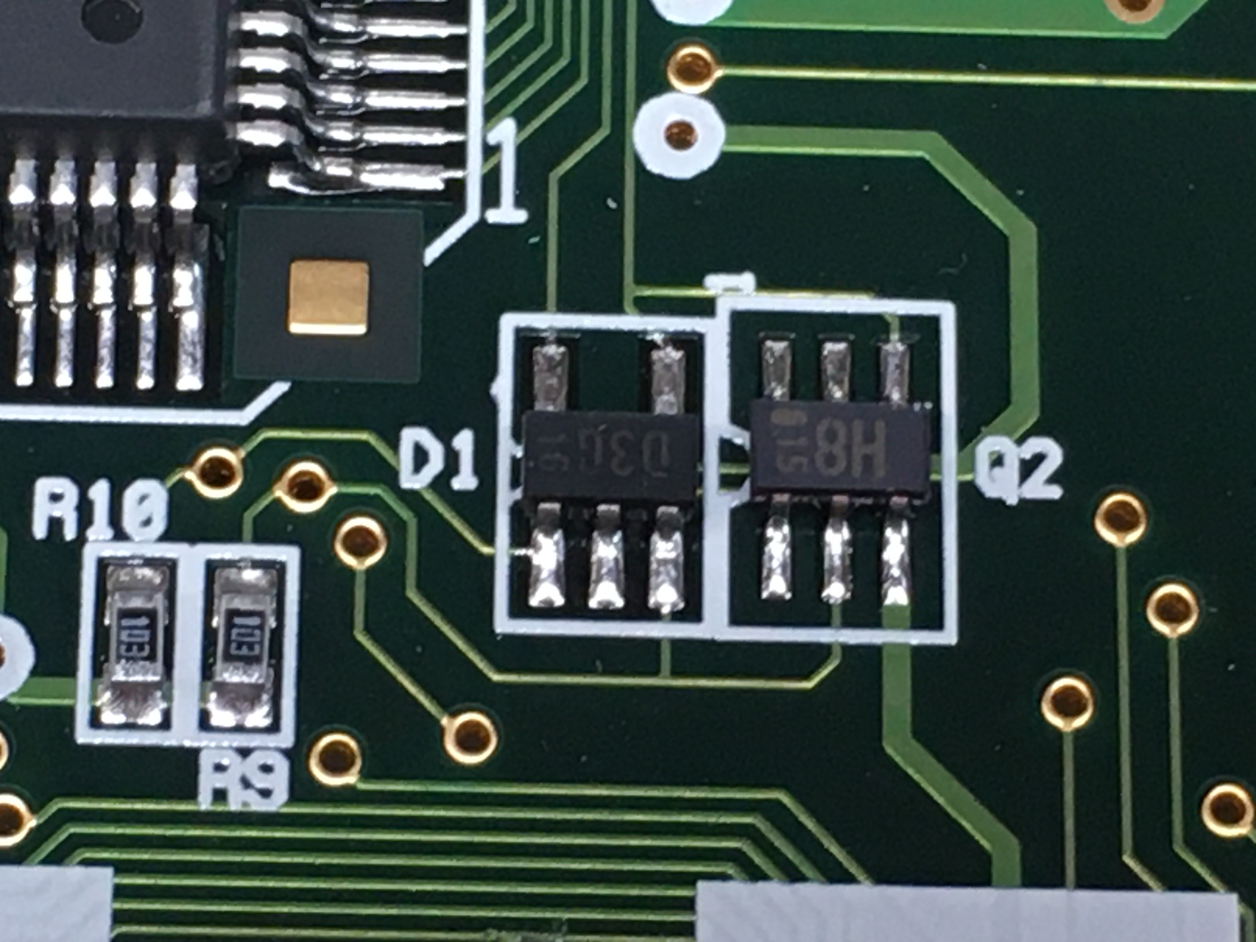
The gold-plated squares in the upper/lower left/right are the contact points for the AA cells. Note the fuse (F1) on the lower left - unusual for a calculator.The gold circle and square in the large white silk screen area are the contacts for the CR2032 cell.
The connector on the upper left is the external monitor connector.
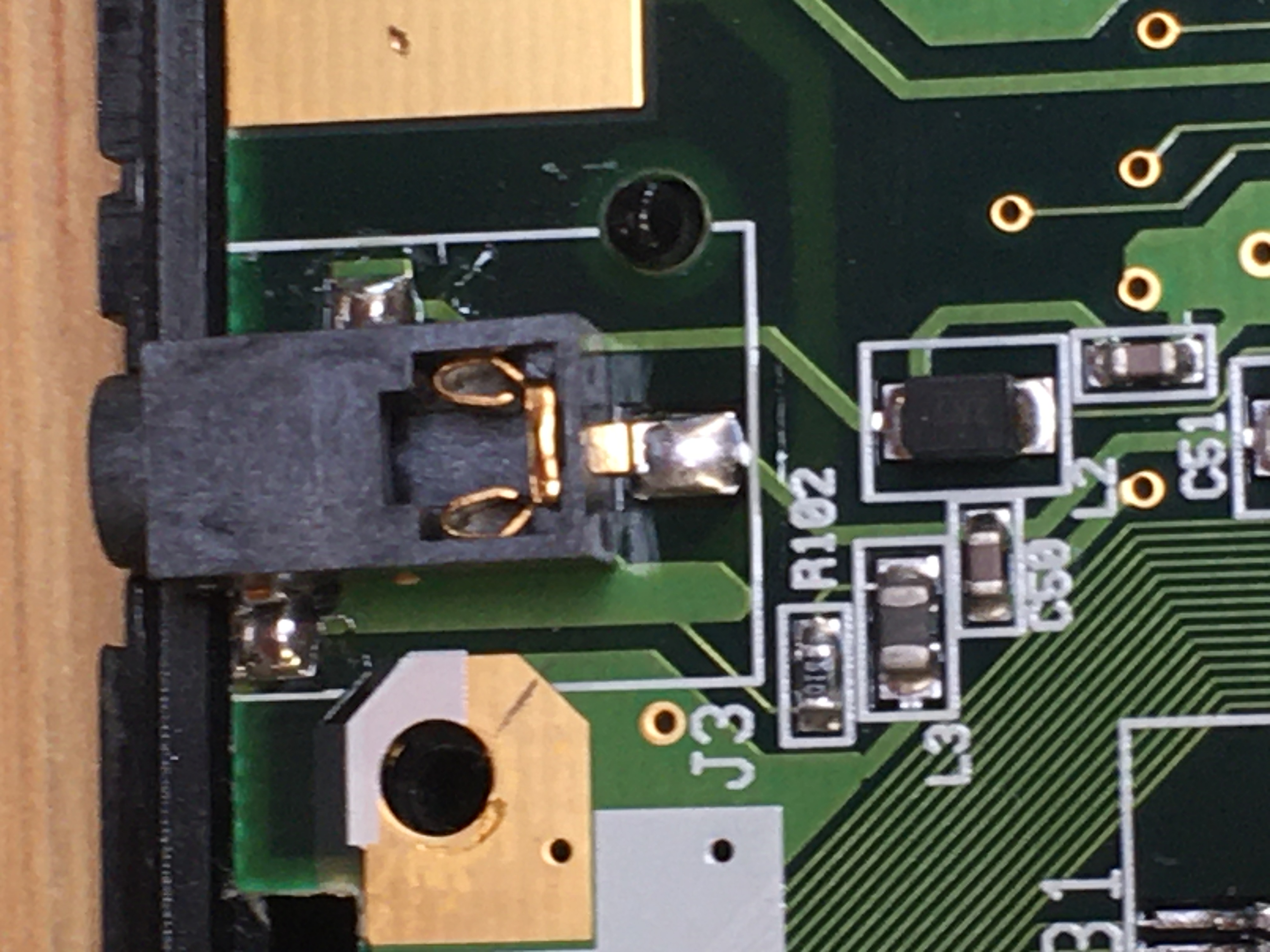
The Tip-Ring connector on the upper right is the serial port.
 The board is very well marked. Everything has a reference designation, most parts have the courtyard marked on silkscreen, and all the chip footprints have the pins numbered. I greatly appreciate this - it's way more than is strictly needed for a general consumer product, but they still took the time to clearly label everything.
There are fiducials on all four corners, and most IC footprints have fiducials as well - never seen that before. (Were they using older pick-and-place equipment that needed more markings? The TI-92 series went into production in 1995.)
Integrated Circuits
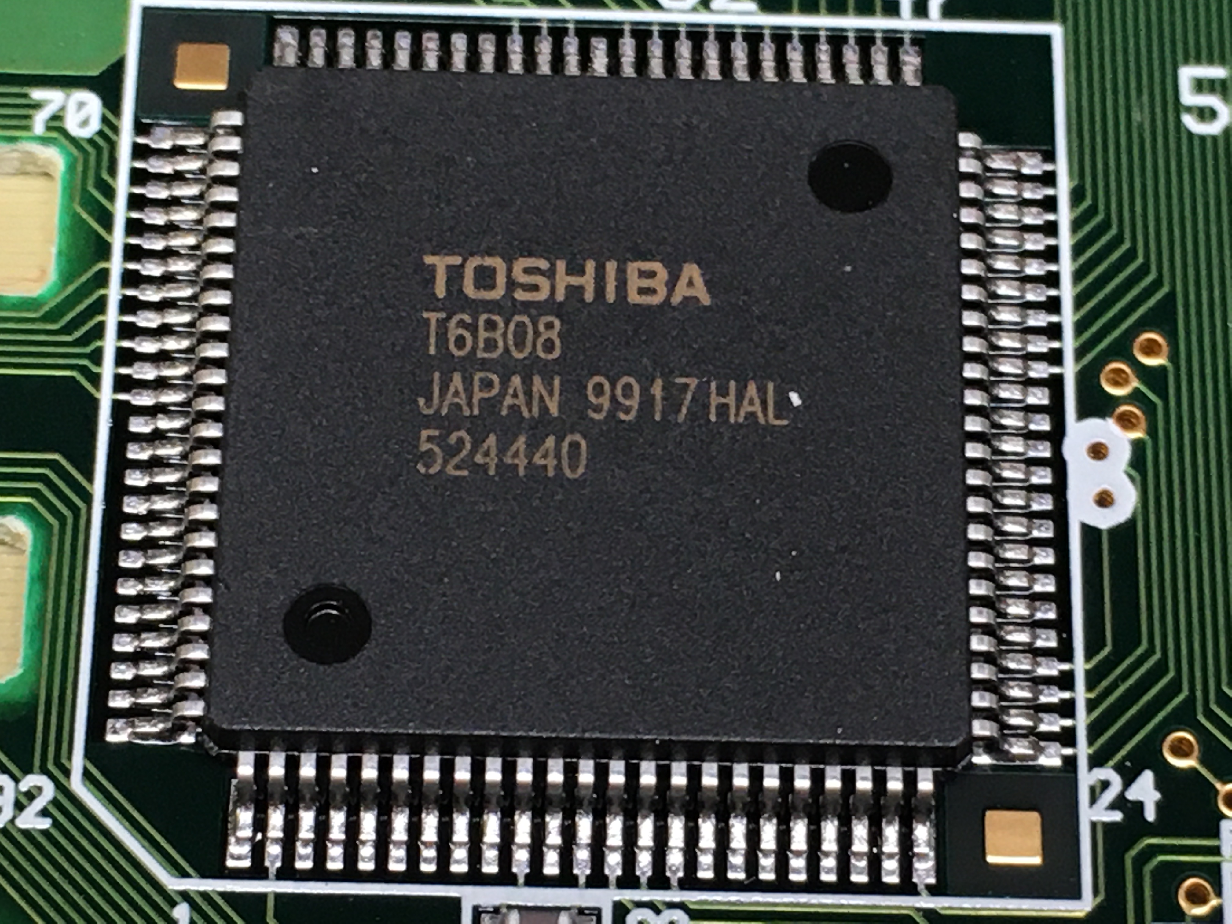
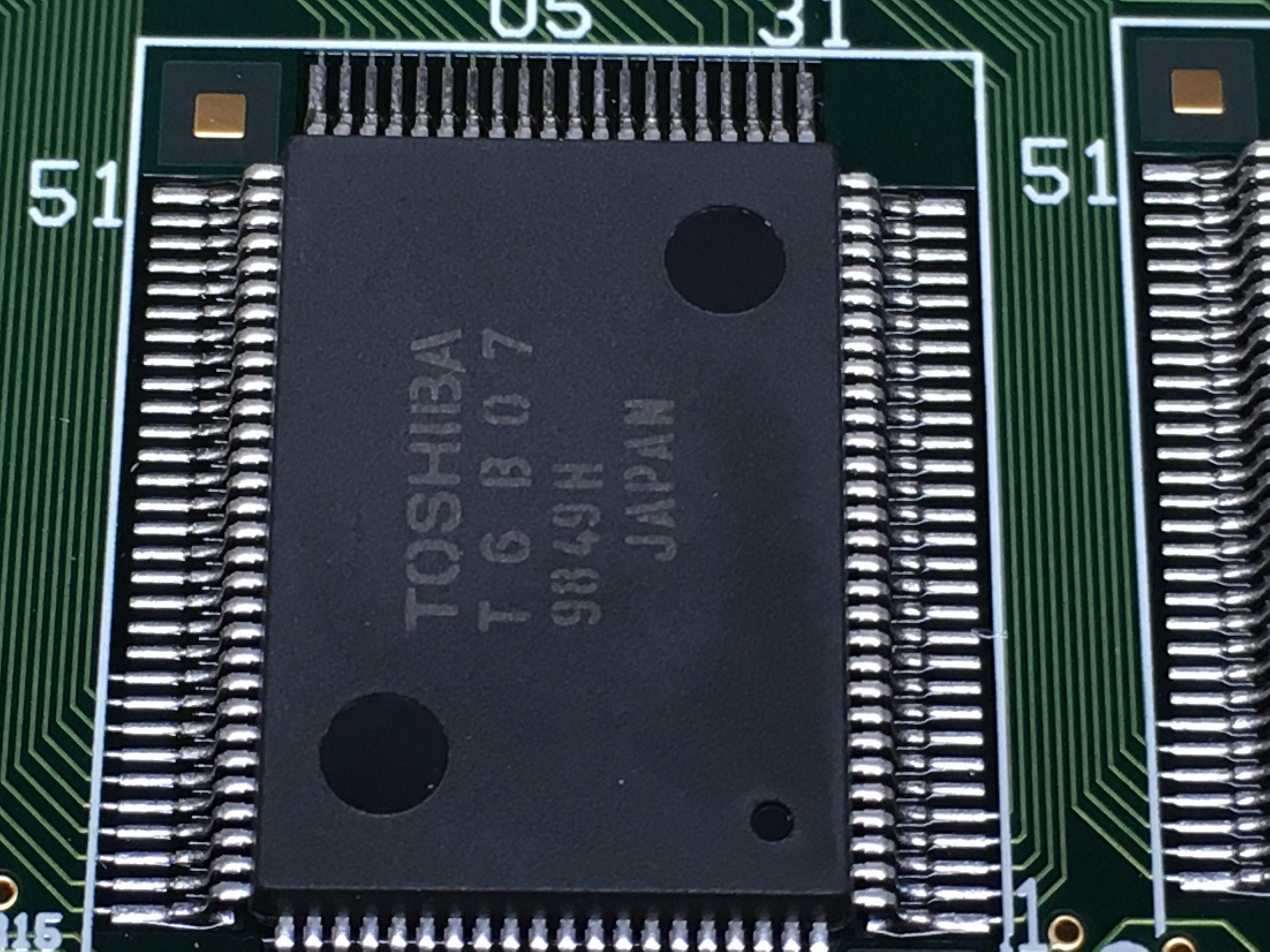
Let's take a look at the chips. The 240x128 dot matrix LCD (and external screen connector) is driven by chips U1 to U5.Parts U1 and U2 are Toshiba T6B08 row drivers, and parts U3, U4, and U5 are Toshiba T6B07 column drivers.
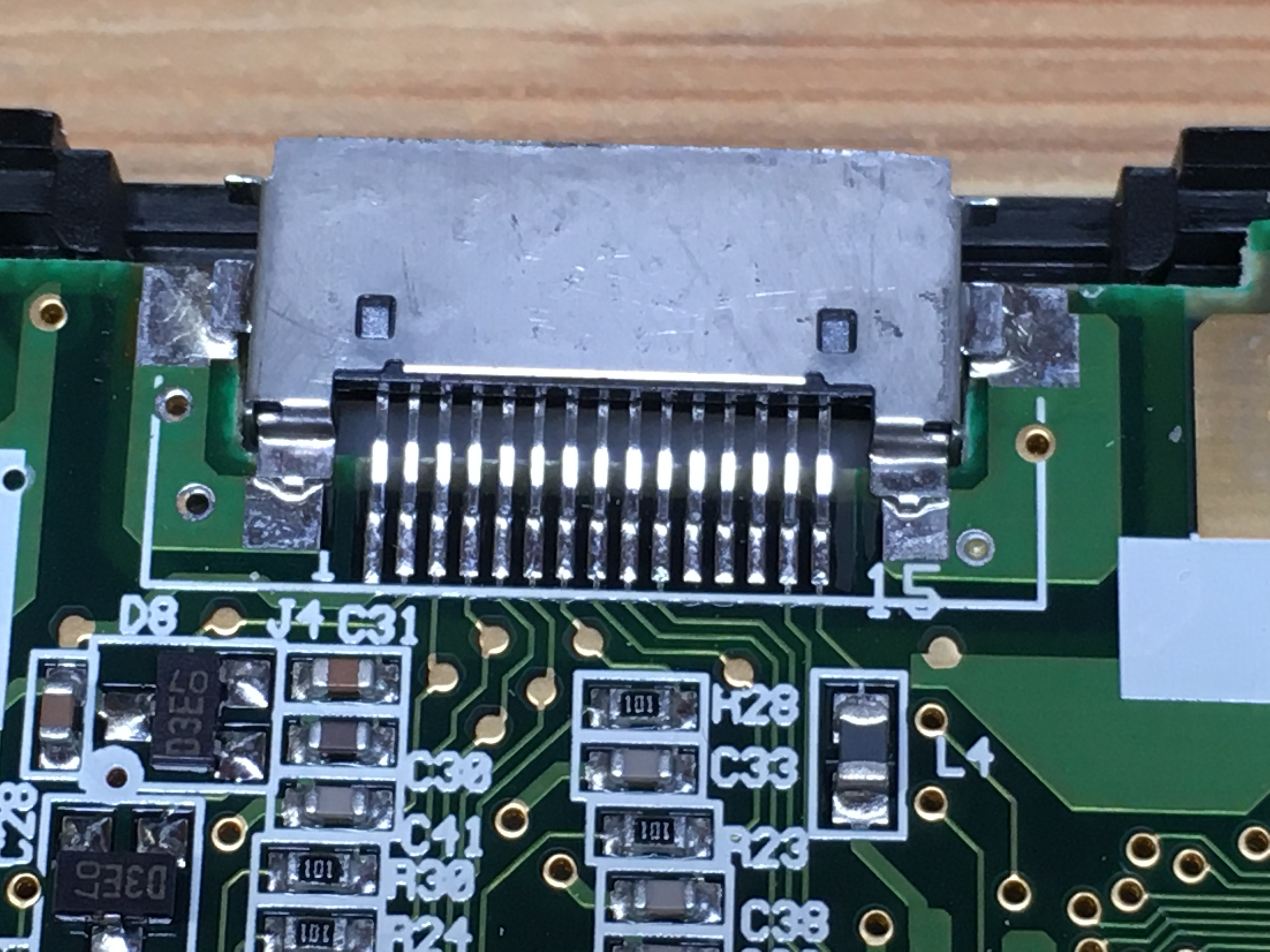
 Closely related is the external screen connector.
When holding the calculator normally, the 15 pin connector points upward from the top-right side of the enclosure. This connected to one of TIs ViewScreen accessories, an external LCD screen intended to be used with an overhead projector. (Remember those?)
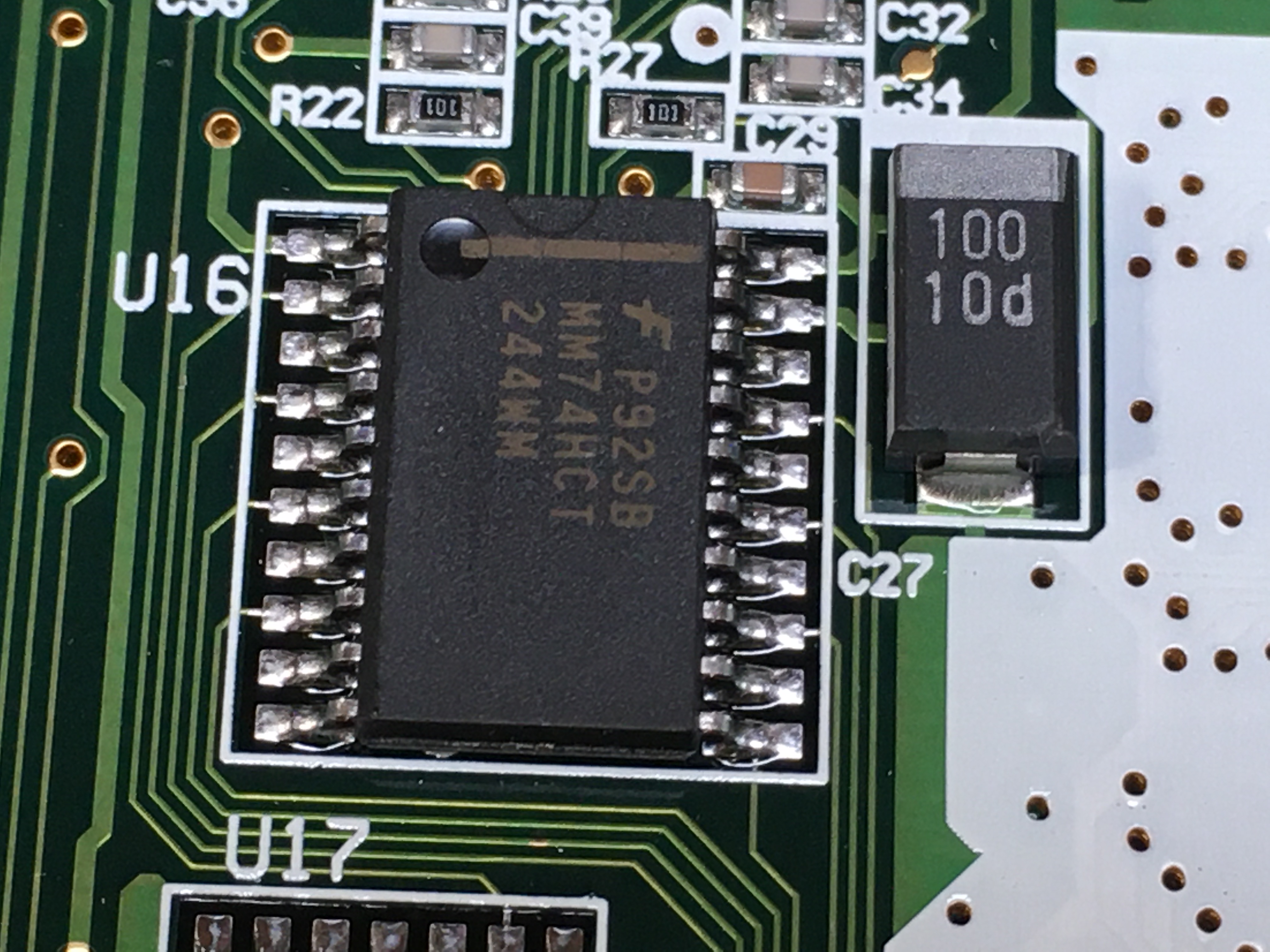
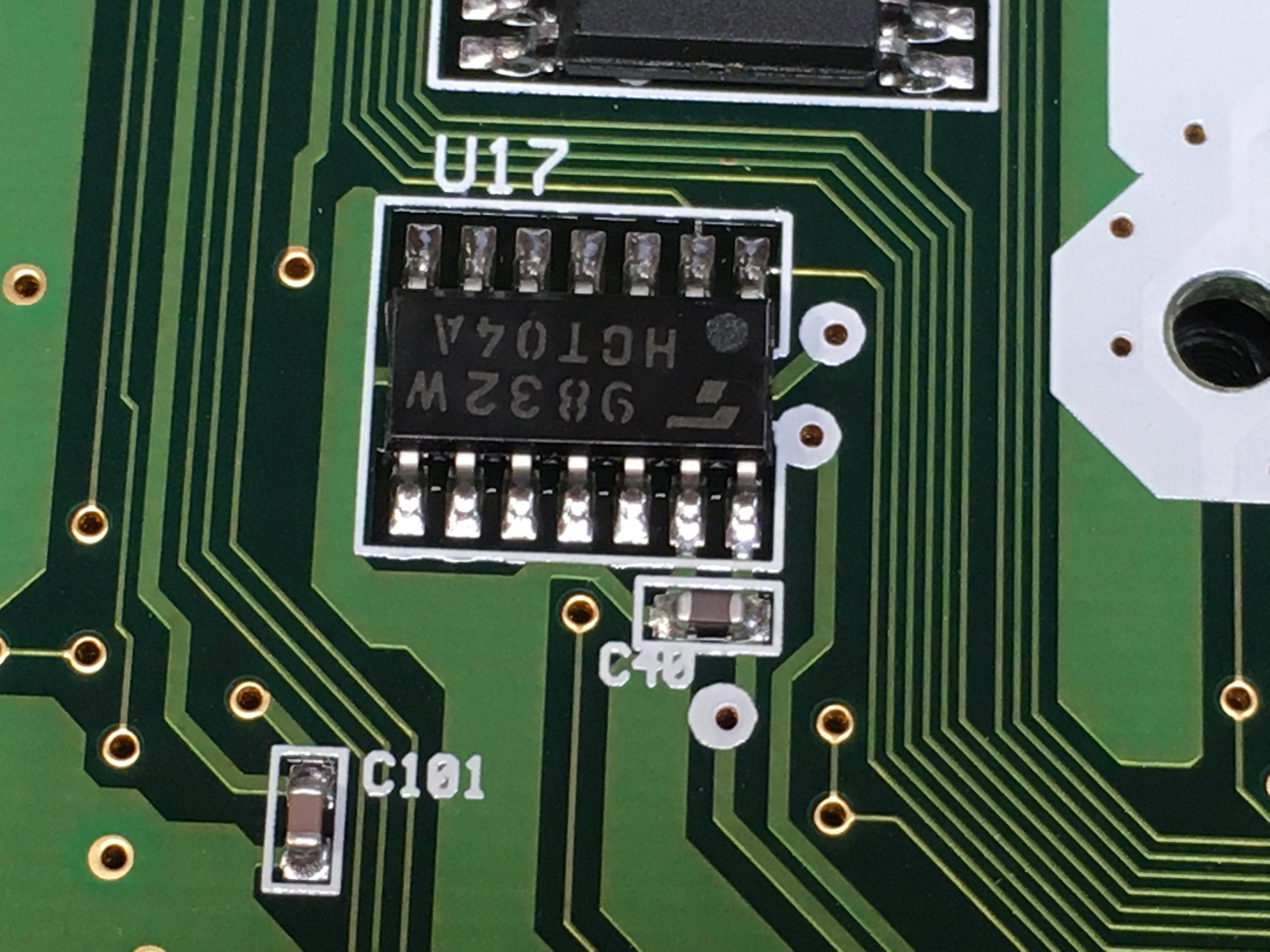
Closely related is the external screen connector.
When holding the calculator normally, the 15 pin connector points upward from the top-right side of the enclosure. This connected to one of TIs ViewScreen accessories, an external LCD screen intended to be used with an overhead projector. (Remember those?)The connector and the protocol are almost certainly proprietary; maybe one day when I have nothing much going on I'll wire up a logic analyzer and see whats up. The port appears to be directly serviced by U16: 74HCT244, an octal buffer and line driver. Part U17 appears to be related (purely due to geographic proximity) and is probably an 74HCT04A, hex inverter.
 So where do the external screen signals come from?
Directly from U10:
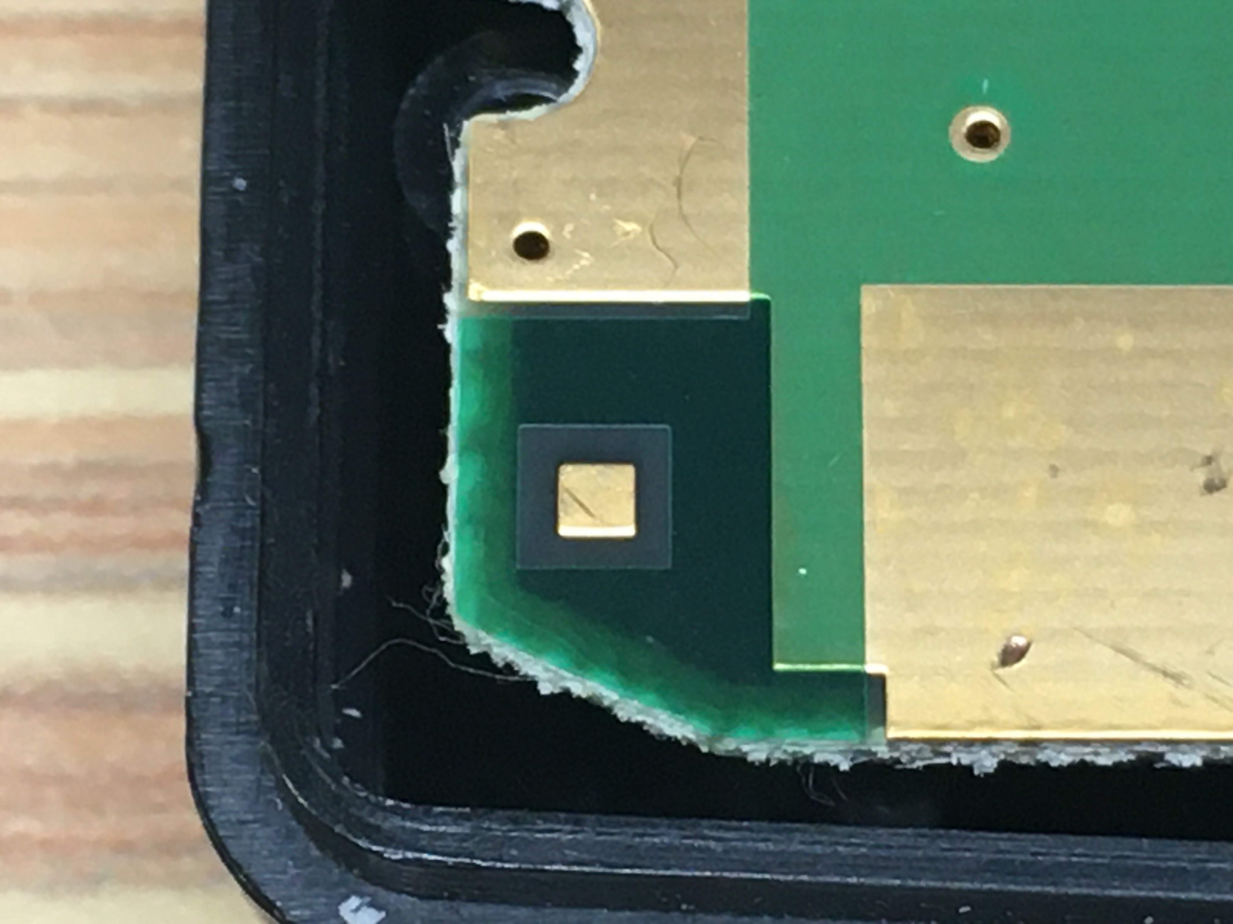
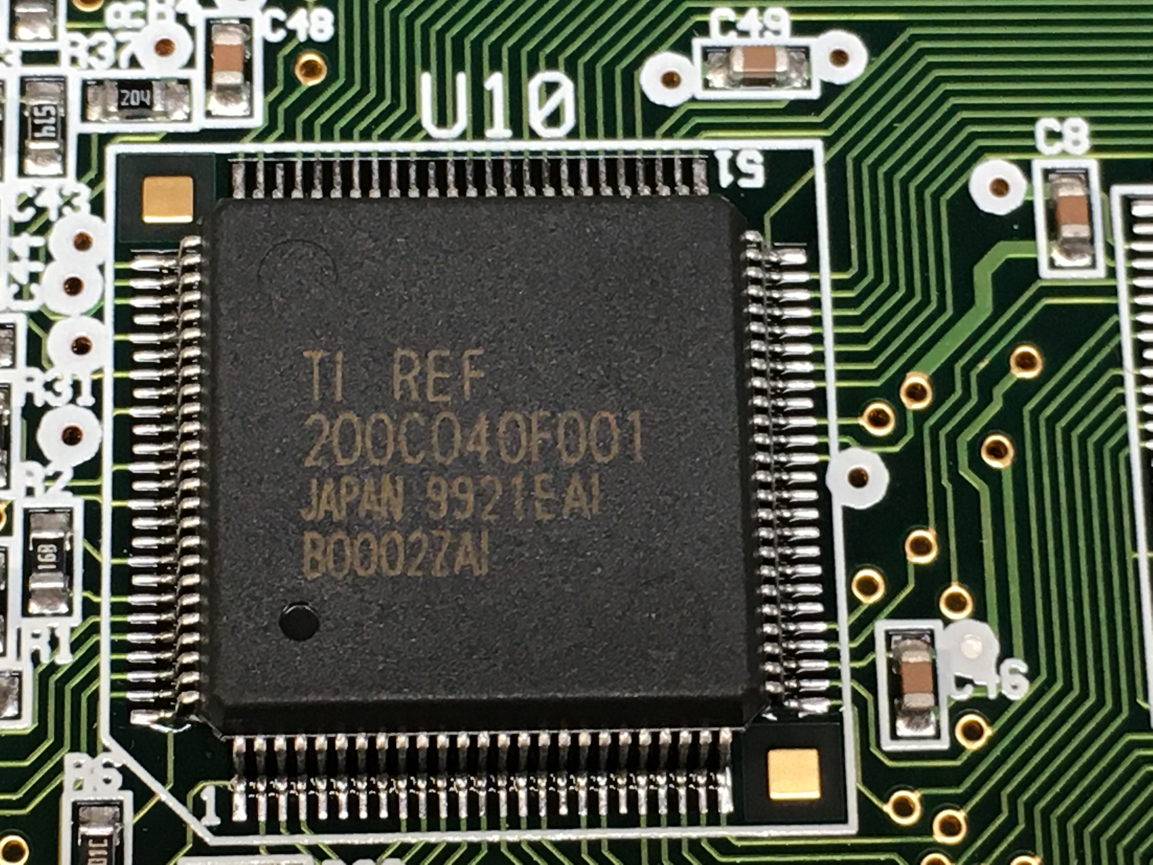 Part U10 -
 200C040F001 - appears to be a TI-proprietary ASIC.Some enterprising hobbyists/fans have figured out some of the functions, but it is essentially a black box. Somewhere in that black plastic logic is generating the signals needed to drive the screens. Processor section:
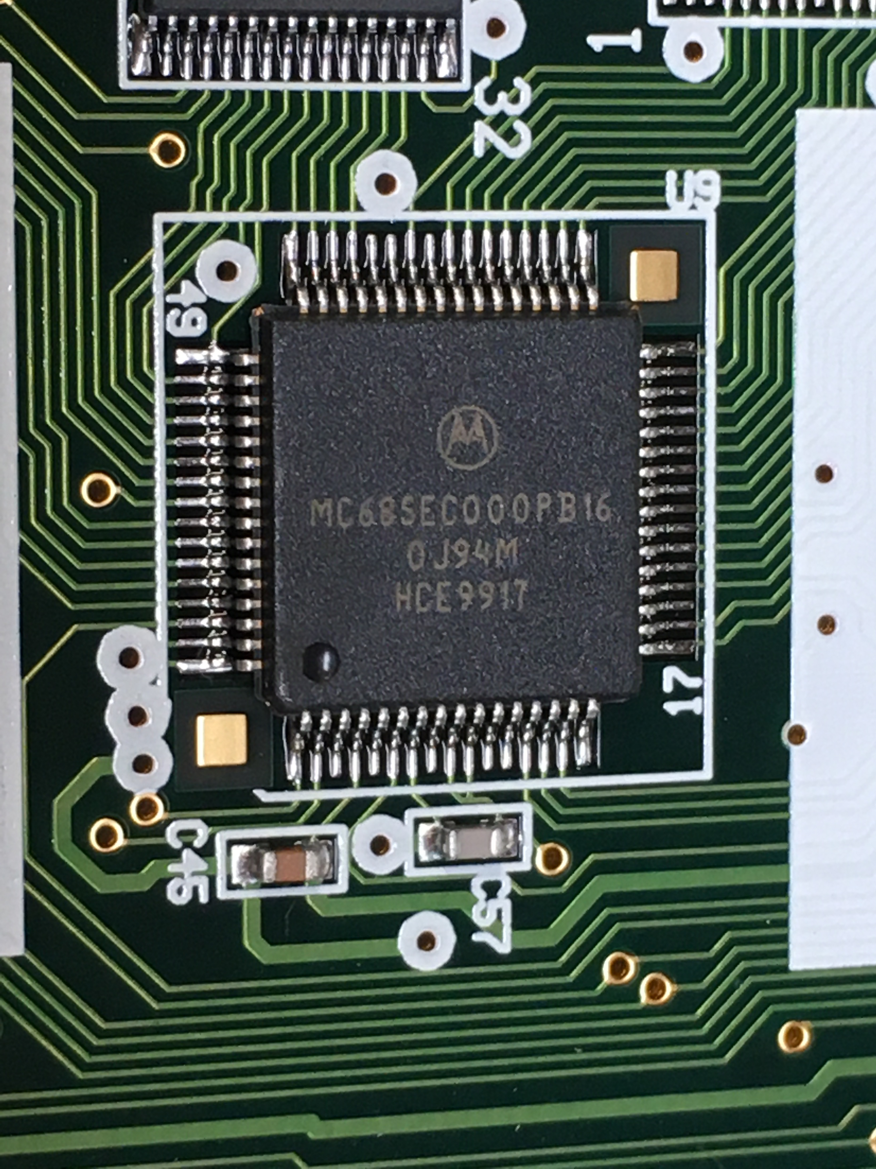
- Motorola MC68SEC000PB16 microcontroller
The heart of the whole system. Still available!
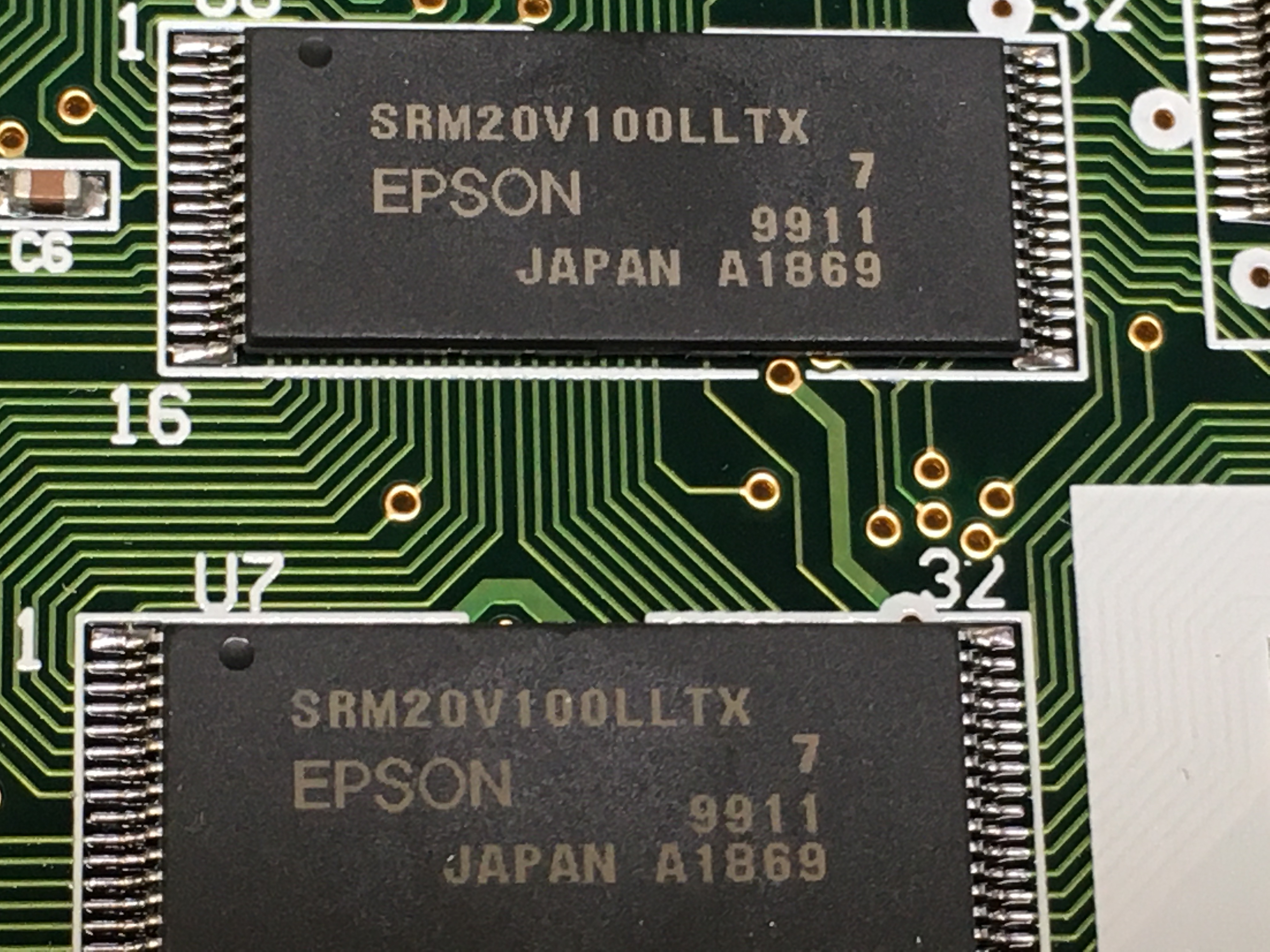
The MC68SEC000 is a 32-bit microprocessor (not a microcontroller, surprisingly) that uses Motorolas famous 68k ISA. This particular part is a variant of the full 68k processor that omits the M6800 peripheral bus, excludes theMOVE from SRinstruction from user mode software, and has an updated, fully static core to reduce power draw. - Epson SRM20V100LLTX(7) SRAM
One Megabyte Static Random Access Memory (SRAM)
Nothing special here: run-of-the-mill parallel interface, static memory.
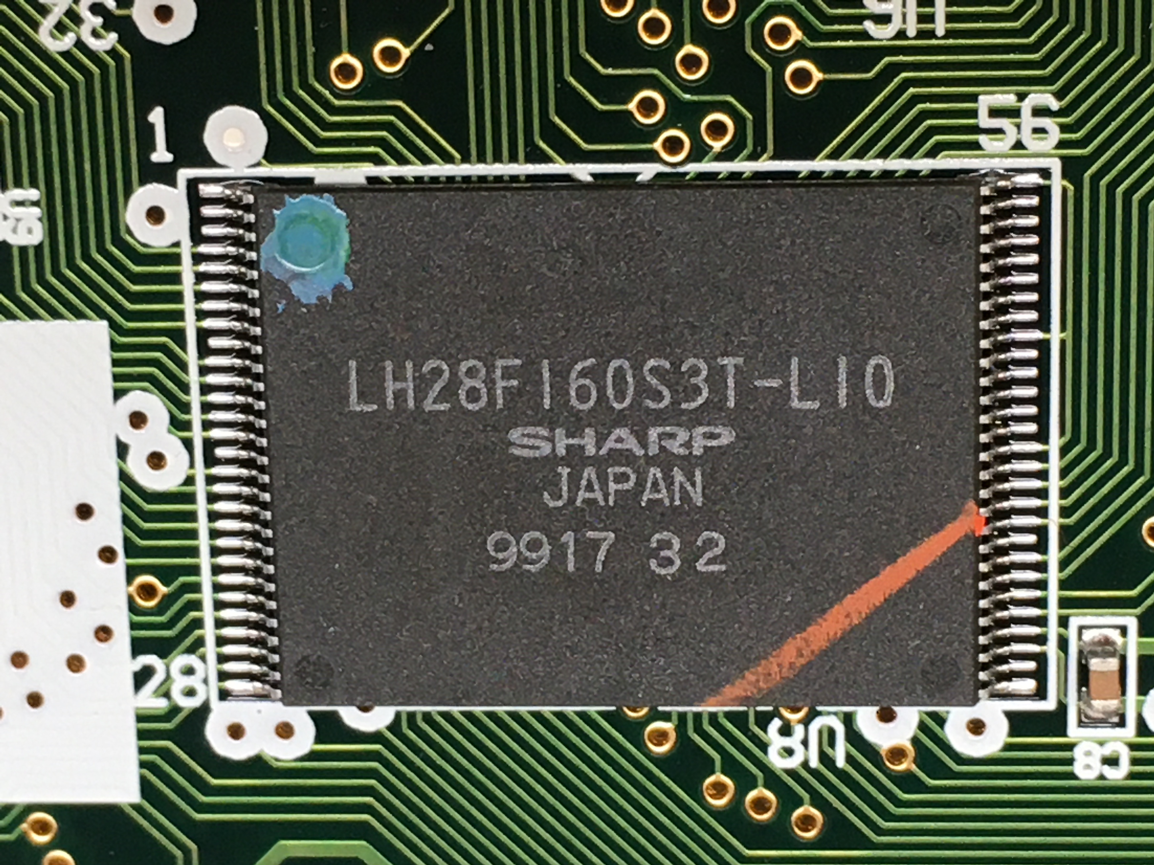
Two chips give the '92 two megabytes of memory. - Sharp LH28F160S3T-L10 Flash Memory
16 Mbit (L10 = 2MBx8) Flash Memory
The 'ROM', presumably! I ordered ZIF sockets for this chip package but was stiffed by the online seller.
Oh well. Maybe a future project to dump the ROM and poke around. That said, 68k ASM isn't my forté.