65C02 Single Board Computer - Dual Channel Servo Controller
Last Update: September 29, 2014
- Introduction
- Features At a Glance
- Block Diagram
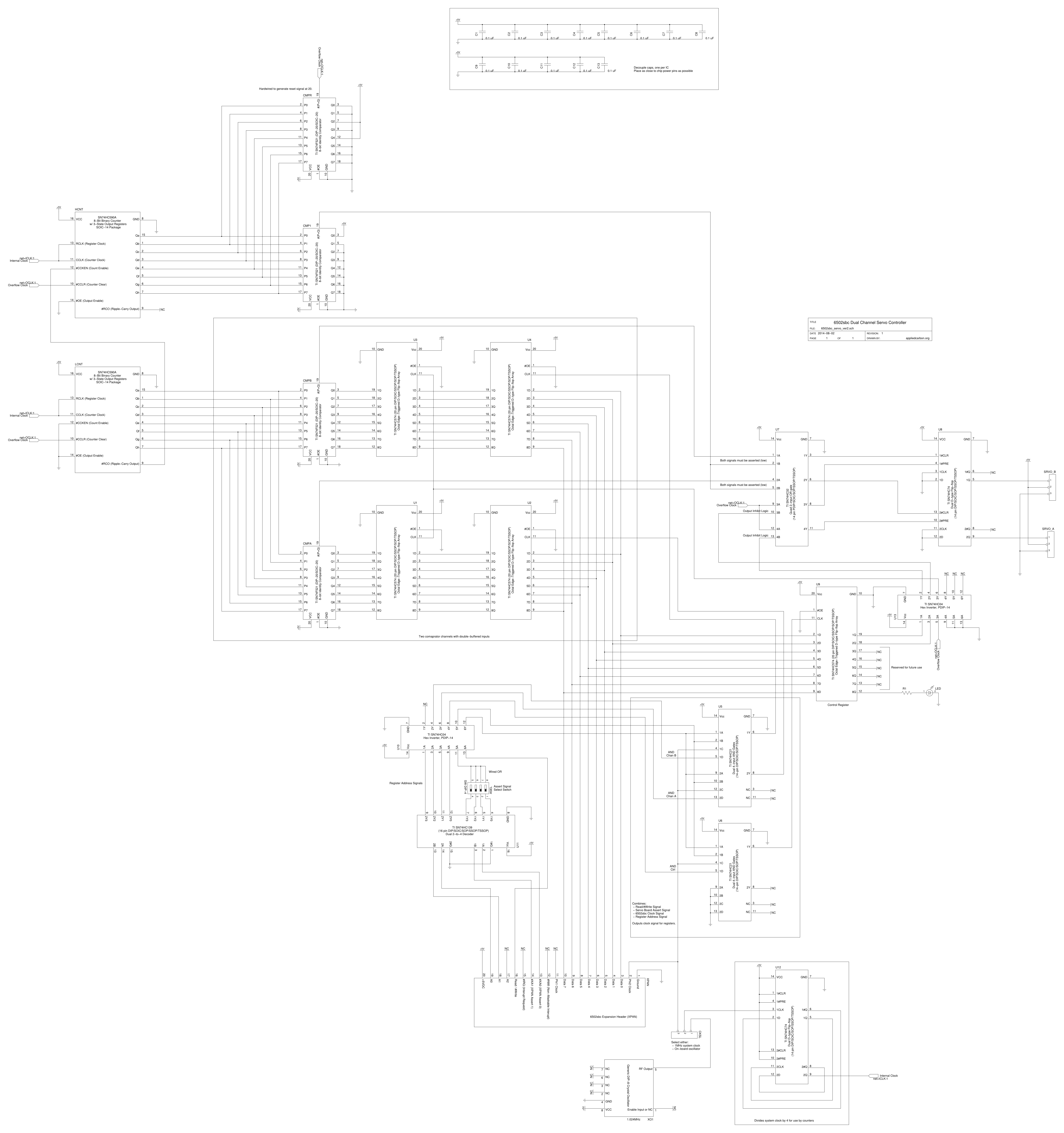
- Schematic Diagram
- Memory Map
- Part List
Note: This project is under development; this document is incomplete at this time and may be inconsistent.
Note: This project is part of an
ecosystem of boards designed around a
65C02-based single board computer.
The basic platform of the BoE-bot kit (and a number of other Parallax kits) is an aluminum chassis with a caster wheel and two continuous rotation servos with attached wheels. These servos have an interface that is identical to the classic hobby servo:
TODO: Signal waveform diagram
This board follows the general ideal set forth in the 6502sbc project: parts that are cheap, generic, and readily available; through hole construction for easy hand assembly; well documented design to encourage investigation and experimentation.
- Drives two "hobby" servos
- Provides 256 discreet steps per servo
- Built entirely from discreet 74HCxxx logic ICs
- Uses standard 6502sbc XPAN expansion header
- User controlled status LED
- 3.050" x 4.000" four layer printed circuit board
- 0.25" mounting holes on 2.750" x 3.700" centers (compatible with Parallax BoE-bot chassis)

Schematic in
EPS and
PNG.
TODO!
| A2 | A1 | A0 | Description |
| 0 | 0 | 0 | 8-bit control register (set bits to 1 to active servo channels) |
| 0 | 0 | 1 | Servo Channel A |
| 0 | 1 | 0 | Servo Channel B |
| 0 | 1 | 1 | Reserved For Future Use |
| 1 | 0 | 0 | Control register (again) |
| 1 | 0 | 1 | Servo Channel A (again) |
| 1 | 1 | 0 | Servo Channel B (again) |
| 1 | 1 | 1 | Reserved (again) |
Note that there can be a max of seven servo channels, but this board only implements two.
Setting/clearing bits in the control register enables/disables each servo channel:
| Bit | Description |
| 0 | Servo Channel A |
| 1 | Servo Channel B |
| 2 | Reserved |
| 3 | Reserved |
| 4 | Reserved |
| 5 | Reserved |
| 6 | Reserved |
| 7 | User/Status LED (on/off) |
A disabled servo channel should be considered 'free-wheeling' i.e. motor is powered but there is no motor drive signal.
