
Apple Newton Benchtop Power Supply (Bespoke, Custom)
Last Update: August 15th, 2026
Table of Contents
Introduction
Recently I attended VCF West 2026 as an exhibitor. My display involved a whole bunch of Apple eMate 300's, a simplified "laptop" for the education market. A few interesting facts:- It was part of the Apple Newton line, and the internal hardware is almost identical to MessagePad 2000 series, to the point where ROM cards from an eMate will boot in a MessagePad 2000, albeit with the screen rotated 90 degrees.
- It was available from March 7th, 1997 to February 27, 1998; just a few days short of a full year.
- It was the first Apple product to use the colored translucent plastic design language, later made famous by the iconic iMac. Unknown if Jony Ive was involved in the design, but he certainly was at Apple at the time.
- It was the first Apple laptop (for various definitions of "laptop") to use an ARM processor, and the last until the release of the MacBook Air M1 in 2020.
Photos
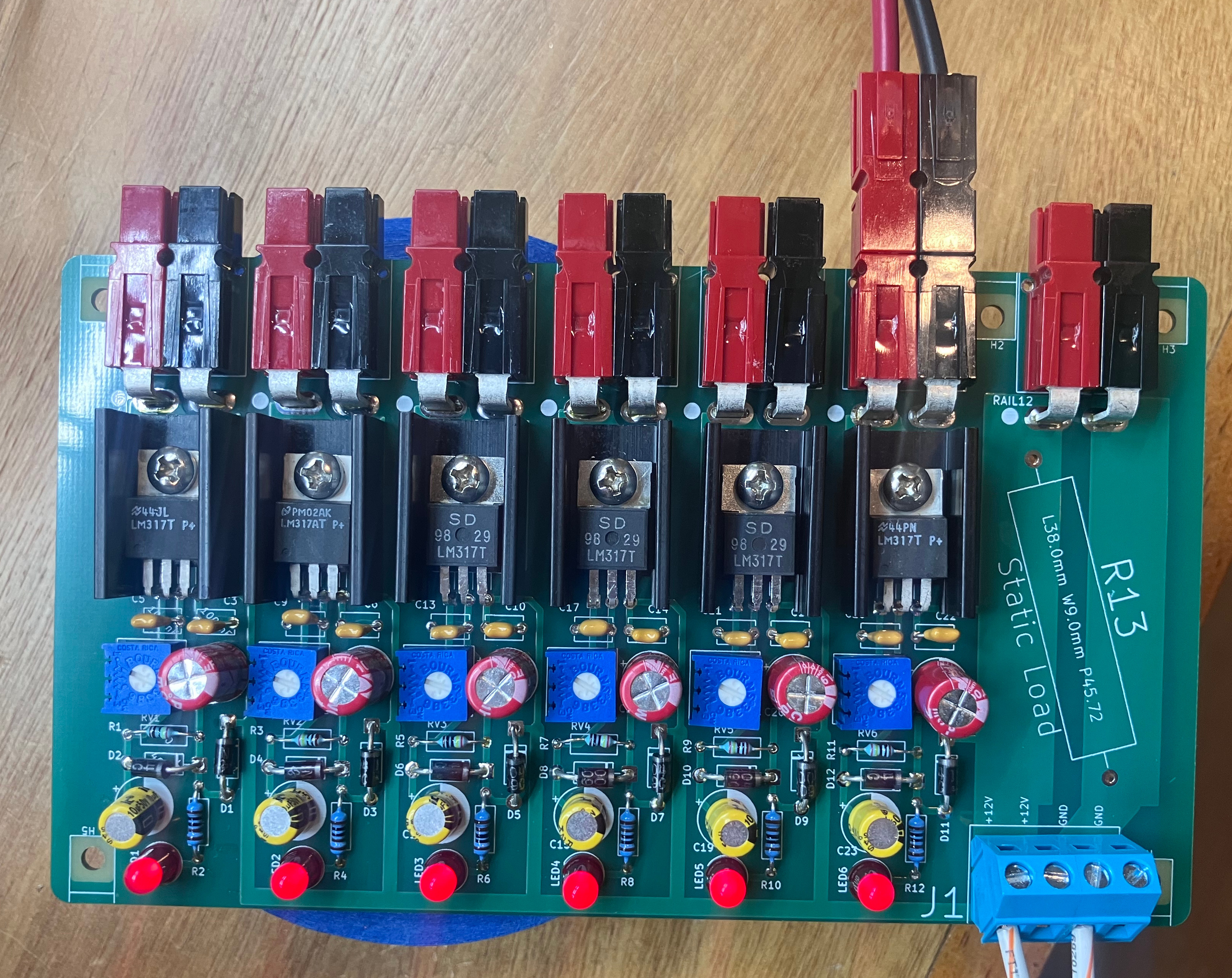
Main Printed Circuit Board
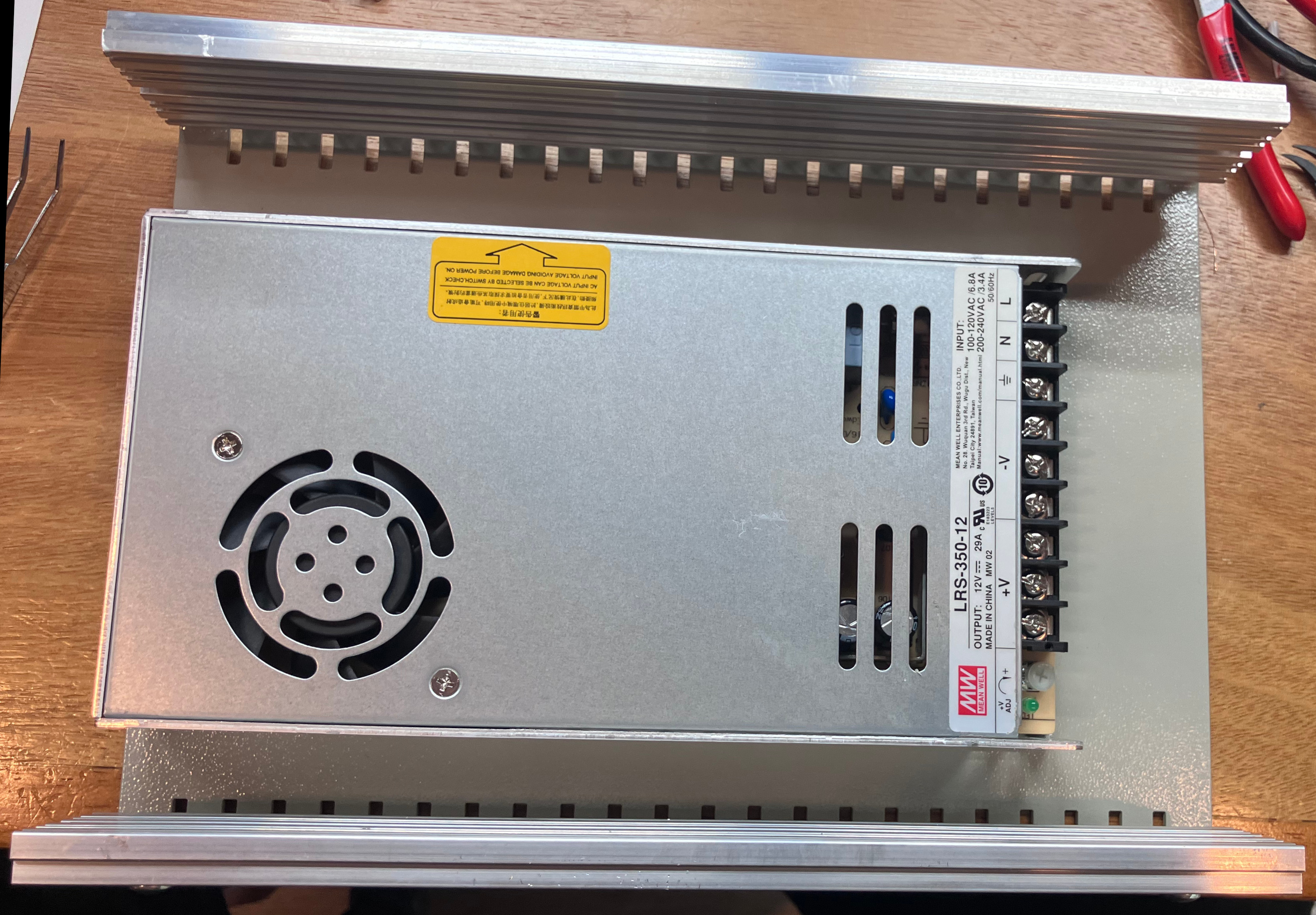
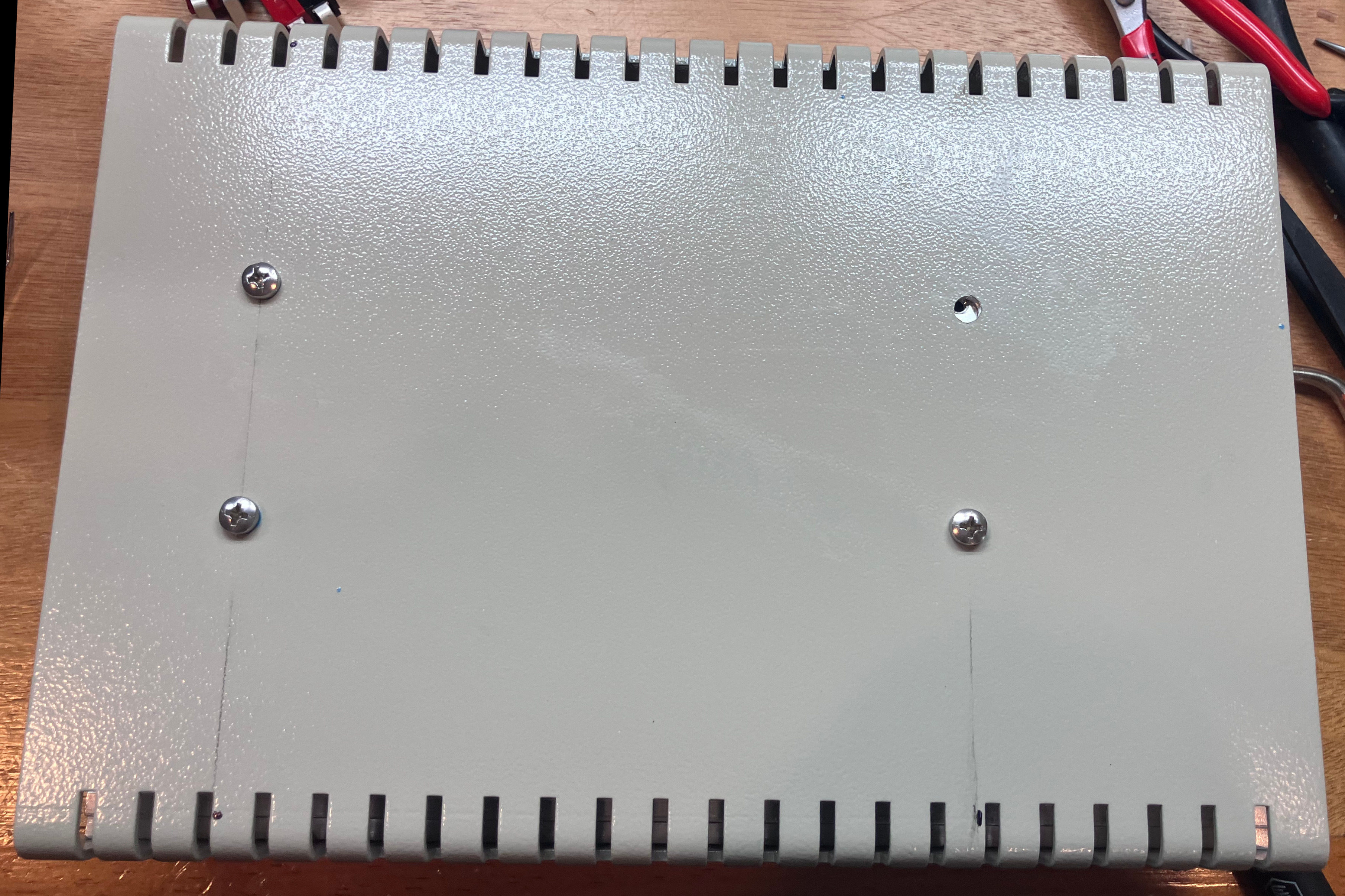
AC-DC converter mounting. Three out of four ain't bad, right?
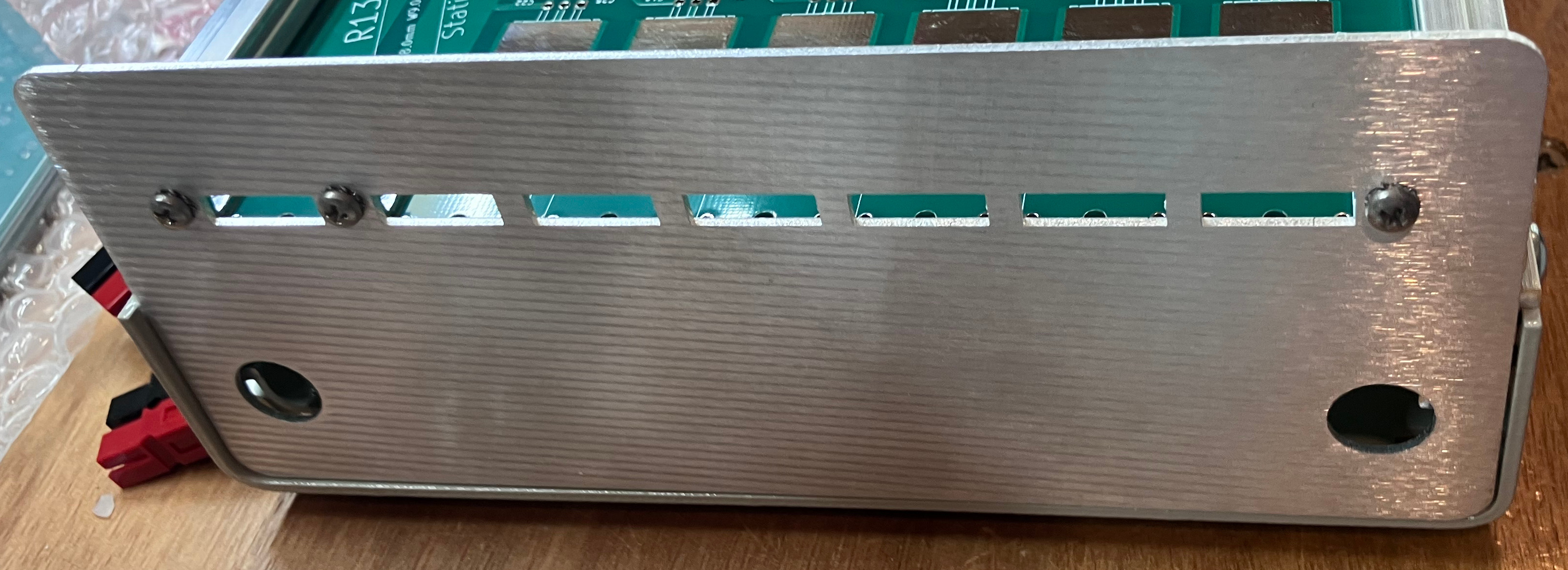
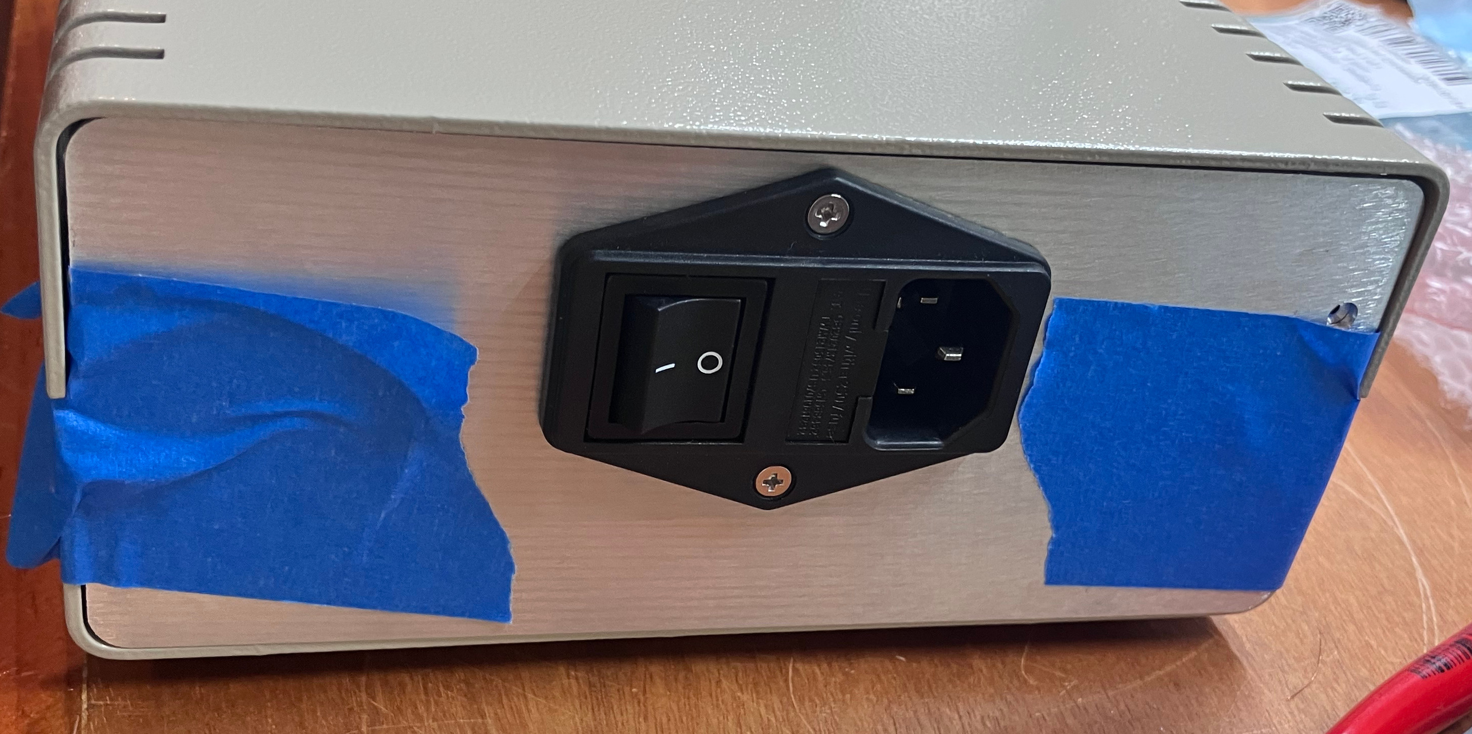
First revision (Rev A) of the aluminum end plates.
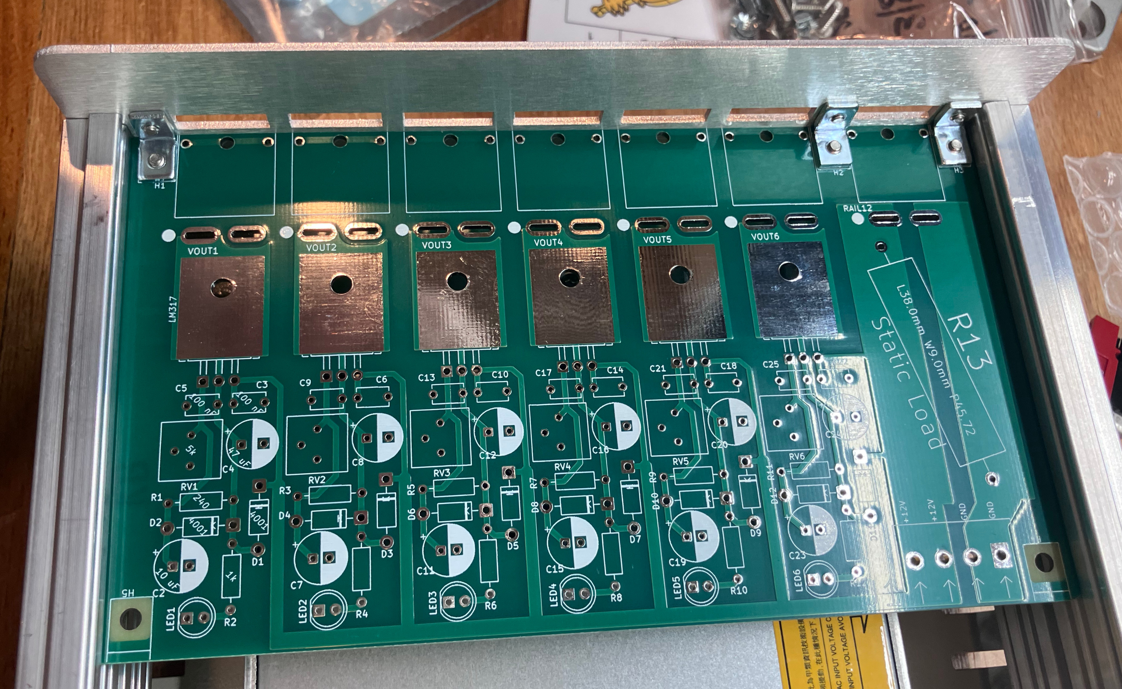
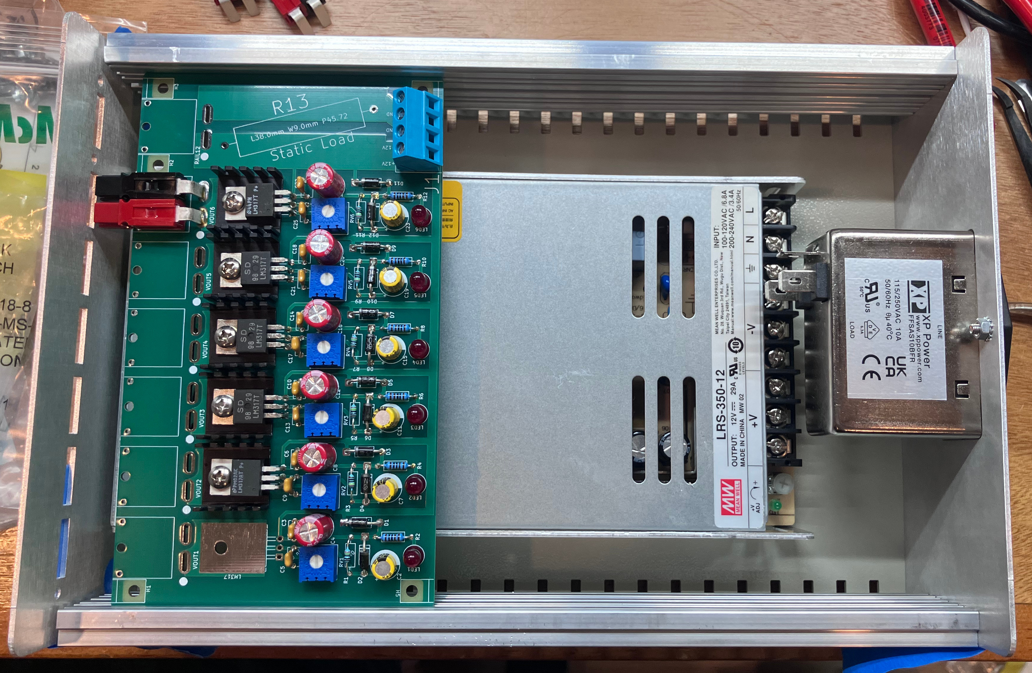
Fit check with Rev A end plates and incomplete PCBA.
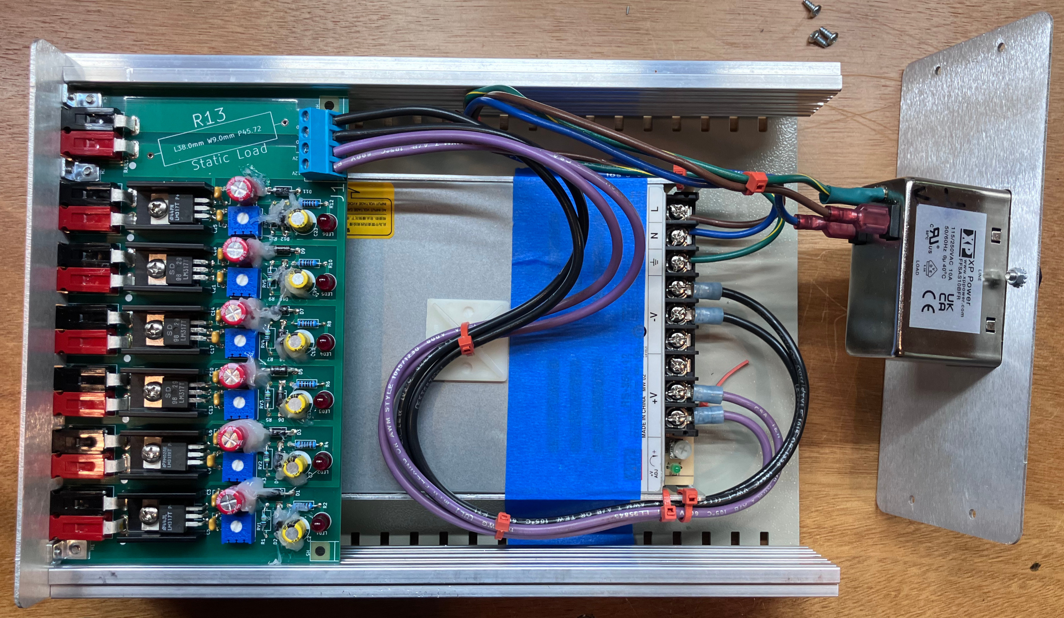
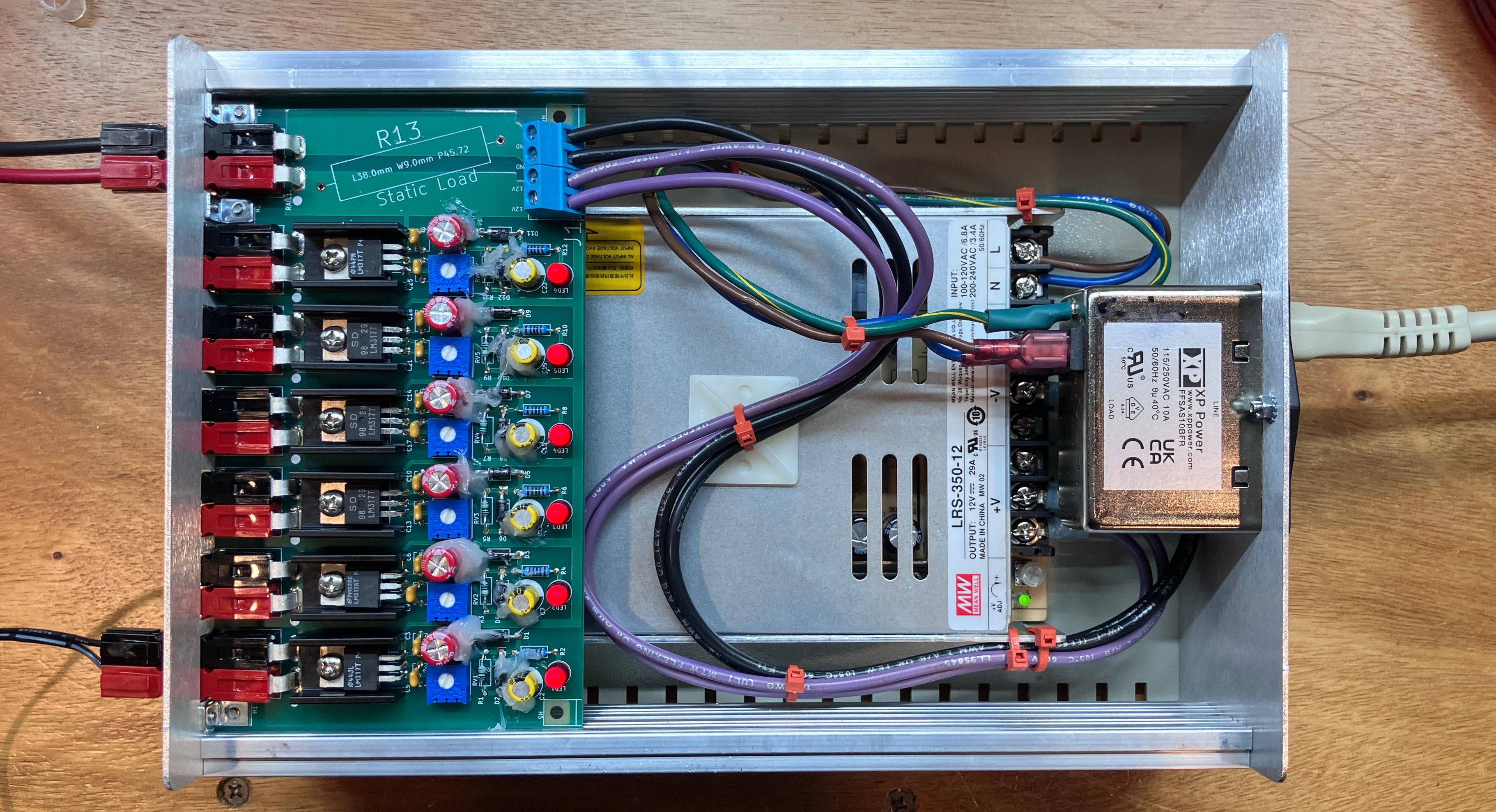
Final assembly with Rev B plates and complete PCBA.
Schematic
Apologies for all the white space. I couldn't fit everything into the next page size down.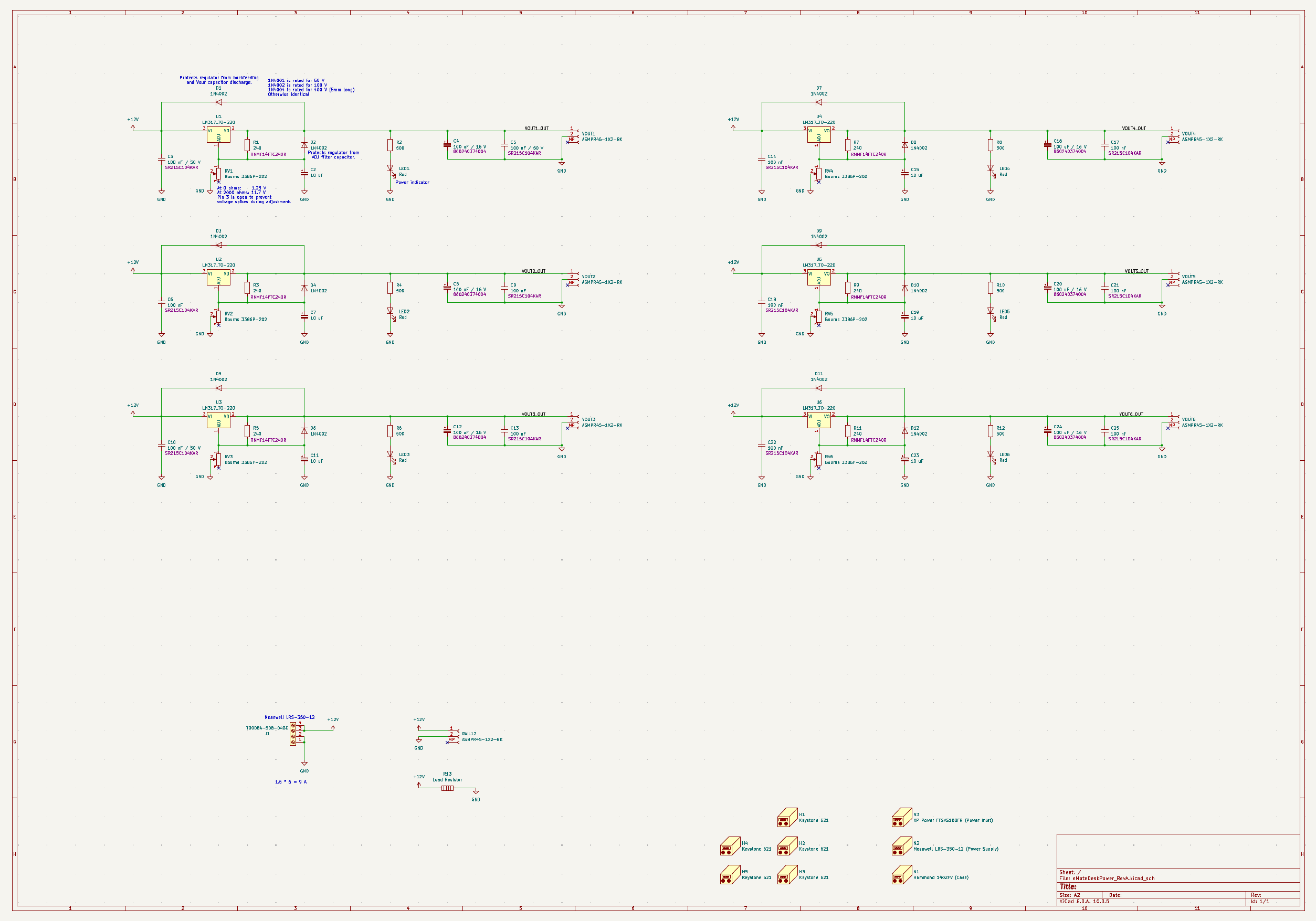
Click for PDF
Theory of Operation
Newton Power Requirements
This power supply is intended to power up to six Newton device at the same time, plus have an external connector for the 12 volt output of the AC-DC converter. All Apple Newton devices require 7.5 volts. The official power supply, Apple Part Number xxxxxx, lists maximum output as 1,200 milliamps (mA). Yes, the required voltage is a bit odd. The original Newton MessagePad devices only use four "AA" cells, so I can't even blame charging a Nickel Metal Hydrid (NiMH) pack for the power supply output. Further, with some bench testing I discovered that eMate 300's only pull about 90 mA (yes, nine-zero, less than 8% of the spec'ed output) - and that's with the backlight on. That said, none of the eMates I own have working battery packs. I assume that 1200 mA rating is a "worst case scenario" specification, and when outfitted with proper battery packs the units will pull some substantial fraction of that 1200 mA to charge the pack. I say "substantial fraction" because the Newton power supplies are actually quite tiny (roughly the size and shape of the average wallet) and the power cable is surprisingly thin. Given the lack of size and heft, I'm pretty sure the Apple-branded power bricks wouldn't be able to provide a full 1200 mA at any voltage (nevermind the voltage drop due to the cable). Obviously this can be tested, but I really don't want to sacrifice a rather rare item just out of curiosity. Regardless, I naively designed this power supply to support 1200 mA output continuously on every channel.Power Supply Design
Power processing and distribution board.
The Printed Circuit Board (PCB)
Each output channel is a generic LM317 circuit, pulled directly from one of the myriad of parts specification sheets and application notes that exist out there. I decided to make this thing as "bullet proof" as possible and put in all the optional parts: excessively large output capacitor, diodes to prevent damage from back-feeding and capacitor discharge, a filter capacitor on the ADJ rail, plus a couple of 100 nF caps for good measure. With the exception of the PowerPole connectors (the chunky red-black guys up top), the TO-220 heatsinks, the 240 ohm resistors, and the yellow caps, everything came from my library of parts - and the caps were just because I had run out (!) if 10 uF capacitors, and the heatsinks because I needed ones with a slightly different shape. The red caps were spares from some optical driver project. The machine screws and locknuts for the TO-220 were left over from a contract job. The diodes were just some 400x series power diodes I've had in stock since the Obama administration. Same deal with the LM317s, I think I got those as part of some "grab bag" bulk order. I'm pretty sure the LEDs are older than me, actually: that dim glow is actually 7.5 mA of drive current. They were probably another "surplus sale blow-out" impulse purchase.The PCBs themselves were manufactured by JLCPCB, a company I've used a couple times in the past for both PCB fab and board assembly. OSHPark is my usual go-to, but their prices are linked directly to boards area: 160.1x91 mm works out to $112.90 for three. JLCPCB quoted me $24.30 for five boards (!), but then has the added cost of shipping, customs duties, and taxes which push the final bill up to $77.51. JLCPCB even has the added benefits of using green solder mask (sorry, OSHPark, I just like the traditional colors), free options for alternate copper weight (more on that later), and simply getting it to me faster. It doesn't take a professor of economics to figure out what to do here. OSHPark pricing and shipping can't be beat for small prototype boards, but when the boards reach a certain point in size, JLCPCB is the way to go.
The adjustable resistors are actually 2,000 ohm rather than 5,000 ohm, but that's fine because the AC-DC converter only goes up to 12 volts anyway, and I only need 7.5 volts output. Note that I left one pole of the adjustable resistor disconnected; this is against usual advice. Sometimes the "wiper" will pass over a bad spot or contamination on the track and briefly become disconnected from the circuit. If the "bottom" pole of the potentiometer is tied to ground, when the wiper "skips" a full 2000 ohms will be applied to the voltage divider on the LM317 ADJ pin. In this circuit, the LM317 output voltage is proportionate to resistance of that adjustable resistors; i.e. "high resistance = high voltage". In otherwords: at a full 2000 ohms, the LM317 would output ~11.7 volts. If the wiper skipped when being adjusted, the circuit would shoot 11.7 volts into anything attached. In a perfect world nobody would have anything attached to the output when it was being adjusted (except a multimeter, presumably), but (knowing my dumb luck) I had some concern with the potentiometer changing value if the enclosure was struck hard enough. I'd rather eliminate the chance entirely, so I chose to not hook up that pin of the potentiometers.
Heat dissipation of the LM317s turned out to be a bigger issue than I expected. A back of the napkin calculation put the output power around five-point-five Watts when pushing a full 1,200 mA. What you can't see from the photos above is there are actually two heatsinks on each LM317: one on top, and one on the bottom side of the PCB. This provides enough cooling (in free air) to run a channel at full tilt indefinitely. (No, I have not tried all the channels at full load, lol. I'm sure the results would be catastrophic.) Anticipating issues, I opted for the copper plating of the PCB to be "2 oz" (typical is "1 oz", one ounce of copper per square foot) and put a copper pad on both sides of the PCB. However, I completely forgot to put vias through the board to connect both sides of the footprint. Consequently the only thermal conduction through the PCB is via the (very thinly plated) walls of main screw hole of the TO-220 footprint, and whatever I can force through a steel machine screw. This has been corrected on Revision B of the PCB layout. That said, when the LM317s are pushing 1,200 mA the heatsinks never get hot enough to cause pain if one is to touch them. (Weird metric, I know.) The limit of human pain from heat is generally considered to be around 50 degree centigrade. This strongly suggests the LM317s are around 50° C (I was never brave enough to touch an LM317 directly to find out) which is well below their maximum operating temperature of 125° C (typical, depends on part and manufacturer). Success! I'd love to replace all the TO-220 package LM317s with TO-3 package parts, the classic king of durability and heat rejection, but somewhere in the last few years all the reputable manufacturers stopped making them. eBay has various parts of sale, but then to go for ludicrous prices. Sign of the times, I suppose.
The outputs are pretty simple: the LM317 OUT pin (and tab) are tied directly to the red side of a Anderson Power Products (APP) Powerpole® 15-45 series (a.k.a. PP15-45). These connectors are rated for use up to 55 amps, which is way more than we will need, but they're fairly common and easily acquired, easy to use, and I have an entire box full of shells and crimp contacts. I briefly considered putting "polyfuses" between the LM317 output and the PowerPole connector, but ultimately decided the LM317s had robust enough internal protection circuitry. In theory, the LM317s have thermal overload protection designed to handle short circuit conditions, more-or-less indefinitely.
Mechanical Considerations
I was tempted to just hot-glue everything to a piece of cardboard, but I assumed that wouldn't fly with the VCF West folks. Also, I'm sure I would have managed to absent-mindedly lay my arm on right onto some exposed power terminals during the event, which wouldn't have been pleasant. The case is a Hammond 1402FV. (The "V" means 'vents'.) This was big enough to enclose both the AC-DC converter and the PCB, and also provide a generous amount of ventilation space. I was careful to select a box that didn't require any direct modification or machining - I was under a bit of a time crunch and the last thing I wanted to do was try to coordinate operations on a machine shop. I briefly thought I could also mount the AC-DC converter on a slide-in aluminum plate, but fit checks showed that would both block the exhaust fan on the power supply, and probably interfere with the LM317 heat sinks on the PCB. In the end I did my best to mark up the bottom of the case with holes for the mounting holes on the bottom of the power supply - well, you can see the result above. This was the most janky part of the entire build. I tried to do some of the end plate "machining" (if you could call it that) with hand tools, but was quickly dissuaded. In the end I used SendCutSend, an online machining service to use an abrasive waterjet machine to fabricate end plates from 0.63" 5052 H32 aluminum sheet. I requested deburring but otherwise no secondary operations, and this was a fantastic service: for about $35 total I got both end plates (two different designs) on my doorstep in about five days. Which is great because it took me two tries to get the end plate designs correct, hah. Entirely my fault; I was using Inkscape for the layout (exporting DXF files from an SVG) and had made some simple errors with cut-out sizes, and didn't account for some of the internal geometry of the enclosure. The second revision of the plates were a perfect fit. Def going to be using this service again in the future. The PCB is only attached to the front plate, via three right angle brackets (Keystone 612) and #4-40 screws. Nothing special here, really, but when plugging in the power cables the front panel flexes way more than I would like. I'll probably rethink that in the next revision of the project; find some way to support the PCB from the back.Conclusion and Closing Thoughts
This was really fun! Over the last year and change, all of my projects and work have revolved around surface mount parts, most of which require magnifiers and tweezers to manipulate properly. Having a large board with big, chunky traces and parts I could see without glasses was great. It's a lot harder to mess up the assembly, and I'm not stressing out about sub-millimeter features and soldering debris. Over the convention I came up with a list of changes I'd like to make:- Miscellaneous thermal and layout fixes, as noted above.
- Upgrade the potentiometers with parts that have more turns (more precision in the output voltage), and move them away from the heat sources (less temperature-induced drift).
- As mentioned above, the front face plate flexes too much when plugging something in. Maybe more brackets?
- Adding one or two USB-A Charge Ports would be nice. I found myself at my table trying to use my phone with a battery bank, which seems silly when I had so much power capability sitting in front of me.
- Upgrade or replace the LM317 parts to provide more current output, to support more power-hungry devices.