
Connecting a salvaged Xbox 360 RF module to a desktop computer
Last Update: March 31, 2015
Introduction
I've always been interested in repurposing game consoles. Well, commercial 'white box' hardware in general but game consoles offer relatively high-end computational parts in readily available and somewhat inexpensive packages.In this case, I have an Xbox 360 collecting dust in storage. I wanted to use the wireless controllers with my desktop computer; the console represents a significant chunk of cash that is otherwise doing nothing, at the very least I'd like to put a part of the kit to good use. A brief search indicated that Microsoft once offered a USB 'base station' for the wireless Xbox 360 controllers but apparently discontinued it a while ago.
During my search I ran across reports of people pulling the RF module out of consoles and just soldering USB cables to them. The first person to do this (that I am aware of) is dil Andou; check out his documentation here. He laid the ground work that everybody else built on in subsequent tutorials.
Searching 'xbox 360 as is' on eBay turned up a large selection of consoles in various states of disrepair. I picked up one that appeared to be in good shape for $20 shipped.
Photos
What I did was build a small carrier board to hold a USB-B jack, 3.3V linear regulator, and a microcontroller to manage the LEDs and trigger the sync operation: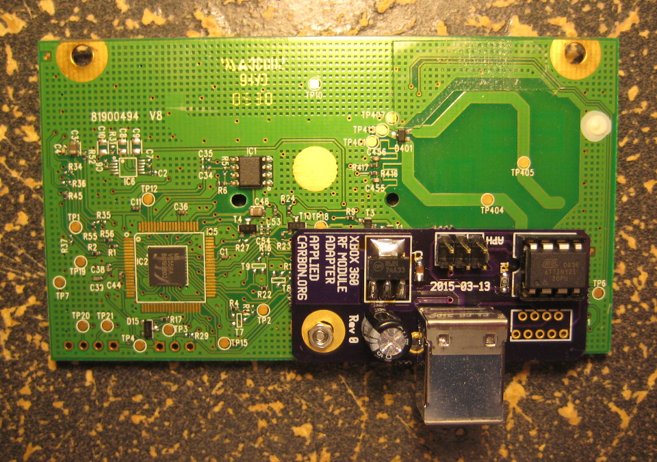 I used a prexisting mounting hole to hold one end of the board. I had to use M2 button head socket cap screws in order to fit under the Microsoft-supplied light pipe face plate. A stack of washers acted as a spacer to keep the boards apart.
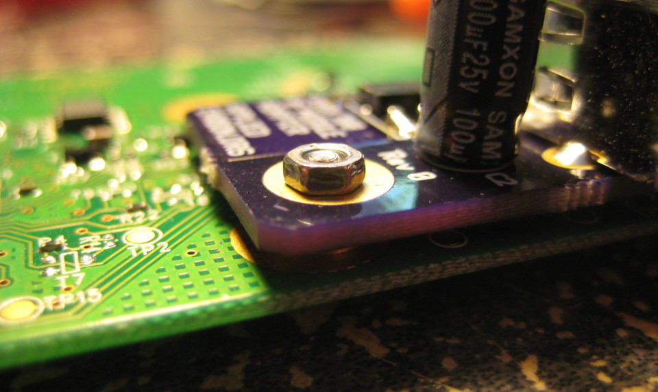 The other side was held apart by wires soldered through the holes left by the (removed) connector on the RF module, and a duplicate of that footprint on my board. I wouldn't use this trick in a professionally developed device, but it works well enough for my purpose. (Note that the RF module connector footprint on the carrier board is actually placed on the opposite side of the board in this photo. Don't base your wiring on the photo below, check out the diagram further down!)
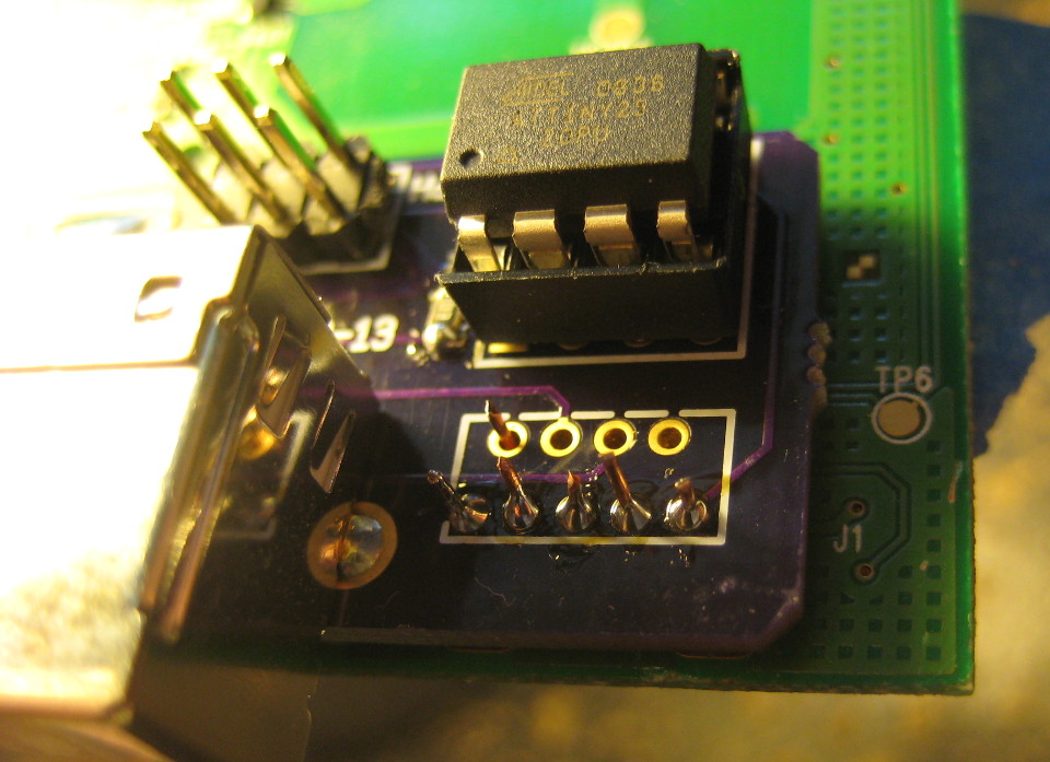 All done! ...Or is it?
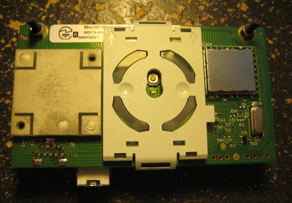 No, no it isn't done. Turns out I got the footprint for the linear regulator wrong. Thankfully nothing burned out when I plugged it in. Some creative soldering and double sided tape was all I needed to fix the issue. (I knew I left that extra space there for a reason.)
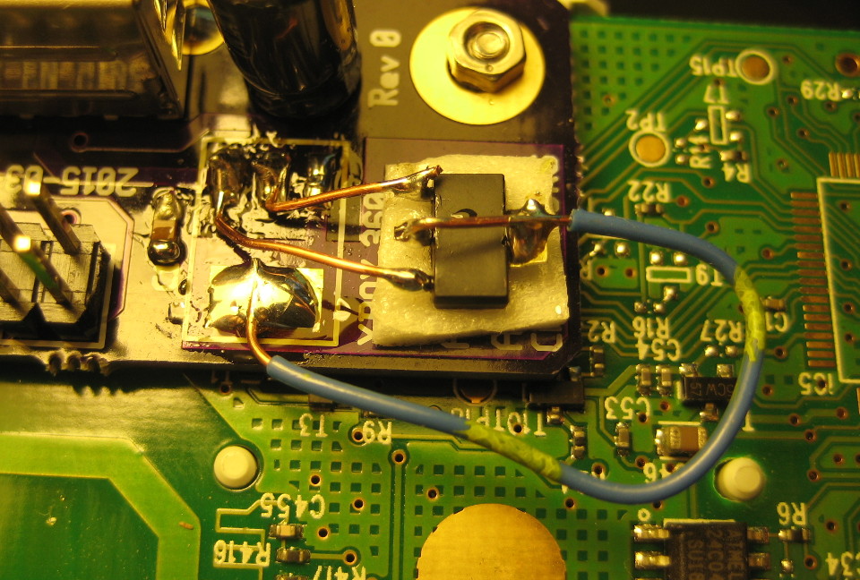 Okay, now it works. Woohoo!
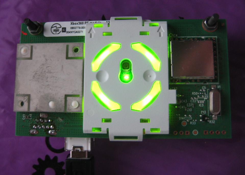
Schematic Diagram
You can snag the schematic in PNG or Encapsulated Postscript (EPS) formats. Note that the RF module runs on 3.3V, not 5V that normally provided by USB, hence the 3.3V linear regulator.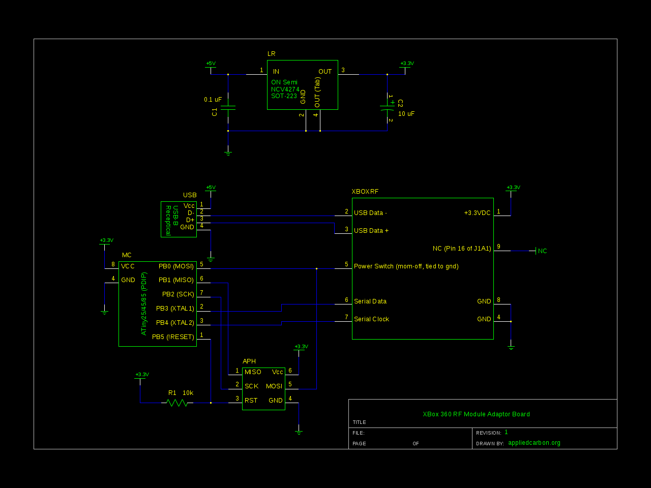
The microcontroller doesn't handle anything USB related, thankfully. Its purpose is to monitor the state of the power switch (a tactile pushbutton) and to send the sync command to the RF module when that button is pressed. It also plays the Xbox boot animation when powered up. Other than that, this project is mostly a wiring job.
Xbox 360 RF Module Connector Diagram
The primary connection for the RF module is a nine pin connector that combines USB signals, power, a propritary serial connecton, and an unused trace.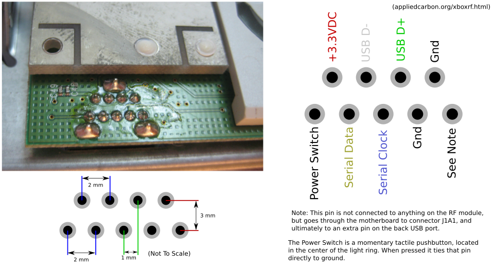 I'm really curious about what the extra trace and extra pin on the back USB jack was intended for. My hypothesis is Microsoft had plans for specialized external prehiprials, possibly a prototype of the Kinect unit, but those devices never made it to production and it was easier/cheaper to just leave the support wiring in place. Still, those custom USB connectors must have cost extra - why leave those in?
A friend of mine suggested that it might have something to do with development of the RF stack on the controllers and receivers. The extra line may have been used to supply the RF module with an analog signal from a controller (or controller development unit), possibly bypassing the RF frontend.
Who knows. You can also grab the gEDA gschem schematic symbol here and PCB footprint here.
Serial Commands
Serial commands are ten bits in length, and are clocked out most significant bit to least significant bit. Interestingly the RF module provides the clock signal for the serial connection. The following is a list of known commands. A big thanks to Astro Rats (whose page is now offline, sadly) for doing some of the inital brute force discovery and the TkkrLab Wiki, whose table I reproduce below without permission (with some modifications):| Data (bin) | Data (hex) | Name | Description |
|---|---|---|---|
| 00 0000 0100 | 0x004 | SYNC | Displays the XBOX 360 controller sync LED sequence, syncs RF module with controlers |
| 00 0000 1001 | 0x009 | CTRLR_OFF | Turns off all controllers |
| 00 0000 01RP | 0x01X | CONFIG | Configures the module (R bit is RF on/off, P bit is 0 for standing orientation) |
| 00 1000 0000 | 0x080 | LED_OFF | Turns off the LED controller |
| 00 1000 0100 | 0x084 | LED_INIT | Initializes the LEDs (required before any other LED commands) and turns on the power LED |
| 00 1000 0101 | 0x085 | BOOTANIM | Same as LED_INIT, plus it runs the Xbox 360 boot animation on the LED ring |
| 00 1000 1000 | 0x088 | LED_INIT_NOPWR | Same as LED_INIT but does not turn on power LED? |
| 00 1000 1001 | 0x089 | BOOTANIM_NOPWR | Same as BOOTANIM but does not turn on power LED? |
| 00 1000 1100 | 0x088 | LED_INIT_BLPWR | Same as LED_INIT and blinks the power LED |
| 00 1000 1101 | 0x089 | BOOTANIM_BLPWR | Same as BOOTANIM and blinks the power LED |
| 00 1010 ABCD | 0x0AX | SET_GREEN_LEDS | Sets the four green LEDs on or off (four least significant bits encode green led value) |
| 00 1011 ABCD | 0x0BX | SET_RED_LEDS | Sets the four red LEDs on or off (same as SET_GREEN_LEDS but independent of it) |
| 00 1100 0000 | 0x0C0 | CLEAR_ERROR | Clears any error display (blinking red leds or orange solid) |
| 00 1100 0001 | 0x0C1 | SLOW_BLINK_ALL | Blinks all four red LEDs |
| 00 1100 0001 | 0x0C2 | SLOW_BLINK_1 | Blinks top left red LED |
| 00 1100 0001 | 0x0C3 | SLOW_BLINK_2 | Blinks top right red LED |
| 00 1100 0001 | 0x0C4 | SLOW_BLINK_3 | Blinks bottom right red LED |
| 00 1100 0001 | 0x0C5 | SLOW_BLINK_4 | Blinks top left red LED |
| 00 1101 0000 | 0x0D0 | CLEAR_ERROR | Clears any error display (blinking red leds or orange solid) |
| 00 1101 0001 | 0x0D1 | FAST_BLINK_ALL | Blinks all four red LEDs |
| 00 1101 0001 | 0x0D2 | FAST_BLINK_1 | Blinks top left red LED |
| 00 1101 0001 | 0x0D3 | FAST_BLINK_2 | Blinks top right red LED |
| 00 1101 0001 | 0x0D4 | FAST_BLINK_3 | Blinks bottom right red LED |
| 00 1101 0001 | 0x0D5 | FAST_BLINK_4 | Blinks top left red LED |
| 00 1110 0000 | 0x0E0 | CLEAR_ERROR | Clears any error display (blinking red leds or orange solid) |
| 00 1110 0000 | 0x0E1_0x0EF | LED_AMBER | Sets all leds to amber colour |
Firmware
I'm told that if the RF module has been synced with a controller before it is removed from the Xbox 360, it'll continue to work with that controller after it has been removed.I wanted to use my controllers with both my (still intact) Xbox and this RF module so I needed a way to resync at will. Thankfully, the power switch on the front of the Xbox is just a button that momentarily connects the appropriate pin to ground. I use an Atmel ATTiny25 microcontroller to monitor that pin, and then send the sync command to the RF module when it detects a button press. I hacked this code together in about and hour, and it represents a 'good enough' solution so expect occasional anomalous behavior. The firmware is released for free (no license) for any use. [Update 2016-04-10] If you're not picking up a clock signal, give this a shot: I've been informed by one Valerian that the serial clock line of the module he salvaged had to have a pull-up attached. Since my module works without an external pull-up I assume that Microsoft, at some point, changed the design. [Update 2019-03-23] By the way, don't forget that the ATtiny has internal pull-up resistors, in case you didn't add a physical pull-up resistor to your board - thanks Ozzelot!
Installing Windows Drivers
The drivers for the discontinued(?) wireless Xbox 360 controller base station are still available and work with a salvaged RF module, with some modification.- Do not plug in your RF module just yet.
- Go to this page, download the package appropriate for your system, and install it.
- Go to the directory you’ve installed it to and create a backup of the file
Xusb21.inf. Open the original file with a text editor of your choice. - You will find the following block of text in the following sections
[MSFT.NTx86.6.0],[MSFT.NTamd64.6.0],[MSFT.NTx86], and[MSFT.NTamd64]:
			%XUSB21.DeviceName.Wired%=CC_Install, USB\Vid_045E&Pid_028E

			%XUSB21.DeviceName%=CC_Install, USB\Vid_045E&Pid_0719

			%XUSB21.DeviceName.Wired%=CC_Install, USB\MS_COMP_XUSB10

			%XUSB21.DeviceName%=CC_Install, USB\MS_COMP_XUSB20

			%XUSB21.DeviceName.Jump%=CC_Install, USB\Vid_045E&Pid_028F
- Replace those blocks with the following block:
			%XUSB21.DeviceName.Wired%=CC_Install, USB\Vid_045E&Pid_0291

			%XUSB21.DeviceName%=CC_Install, USB\Vid_045E&Pid_0291

			%XUSB21.DeviceName.Wired%=CC_Install, USB\UNKNOWN

			%XUSB21.DeviceName%=CC_Install, USB\UNKNOWN
- Plug in your RF module, sync controllers as needed.