
SpaceX Starlink Consumer Router Teardown
Last Update: May 4rd, 2022
Newest update at bottom of page.2022-05-02: First Contact
Introduction
So my Starlink ground segment arrived. Unfortunately my living circumstances had changed since I placed the order (nine months, almost to the day) and I am no longer able to deploy it.
Stuck on AT&T DSL for the foreseeable future. Bleh. So I took apart the router instead.
Exterior
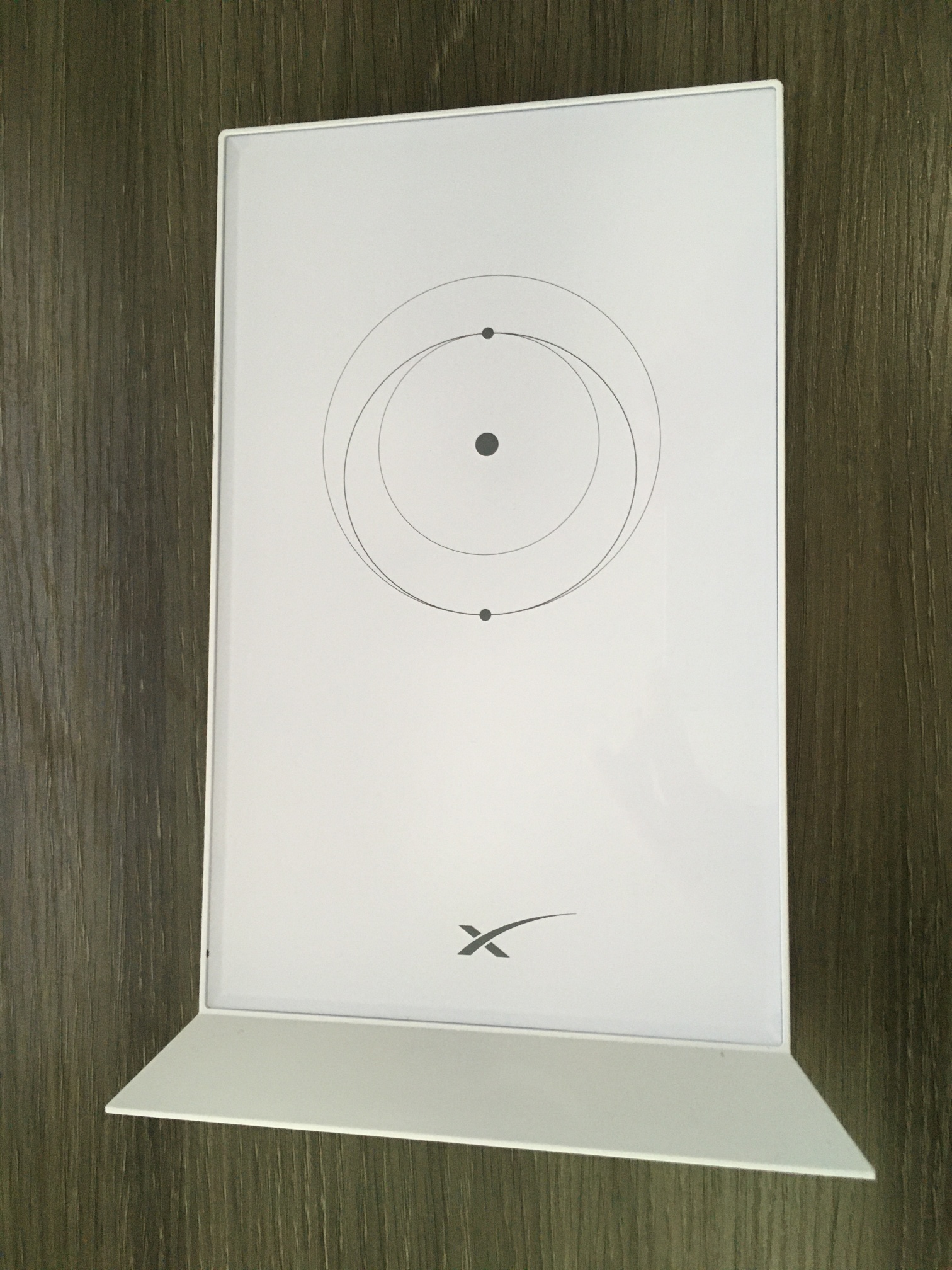
Not quite 'school of Apple' but leaning that direction. Feels very solid. That front panel is glass.
To my immense disappointment, the planets and sun don't light up. Spoilers, but I found references on the PCB to blue and white LEDs - maybe it was supposed to light up at some point?
 The bottom panel was the obvious entry point. It's perimeter was held down very lightly with some kind of adhesive but the primary mechanism were four latching tabs.
 I've been bamboozled! No entry here. That plastic piece is purely cosmetic.
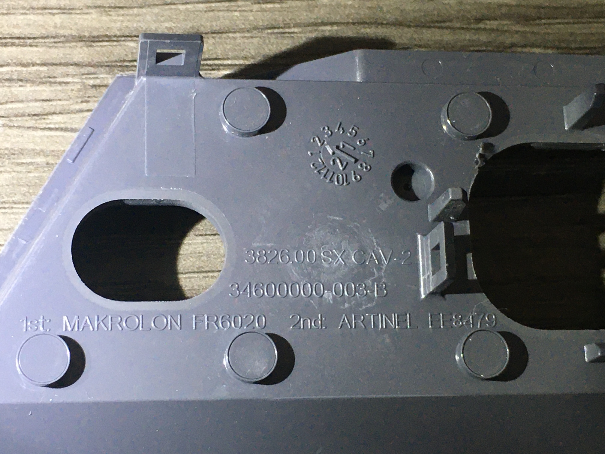 Reproducing text content for the benefit of search engines:
	2/21 (Febuary 2021?)
	3826.00 SX CAV-2
	34600000-003-B
	1st: MAKROLON FR6020 2nd: ARTINEL EE8479
So the entire shell is one piece. Gotta take that glass panel out, I guess.
Some prying revealed naught, the edge readily flexes out of the way but the glass doesn't move at all. Maybe a heat gun to soften up the glue?
 No go, case started melting and the glue seemed completely ambivalent.
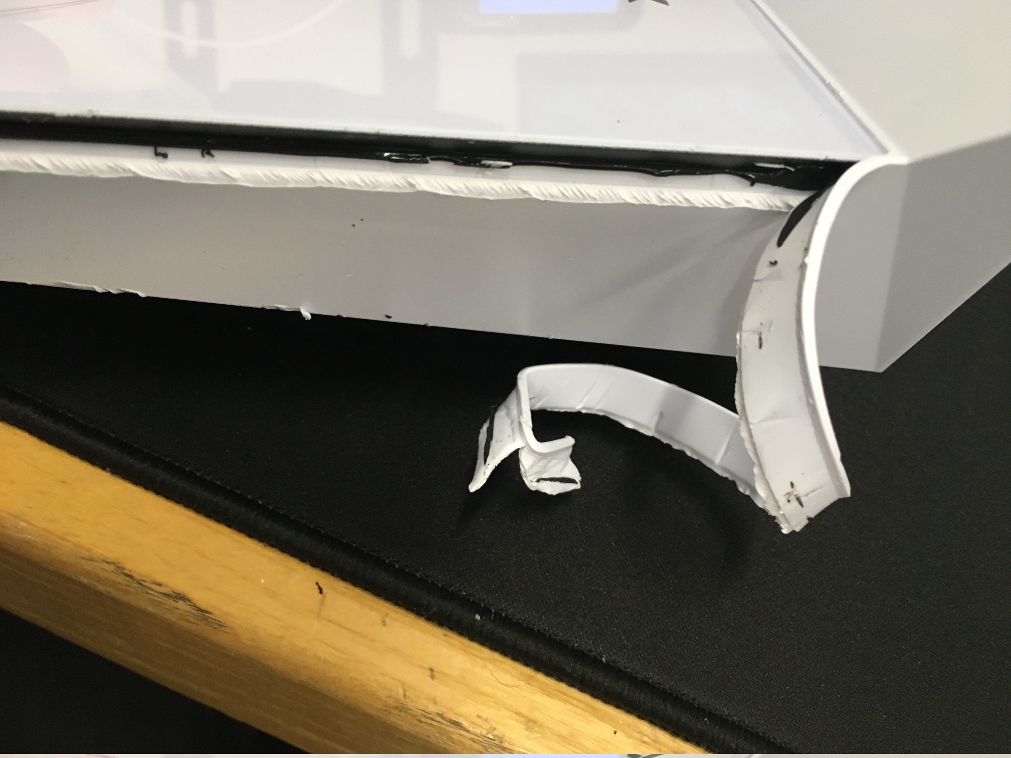
 Oops.
Well, it's already broken so let's just go for it.
Oops.
Well, it's already broken so let's just go for it.
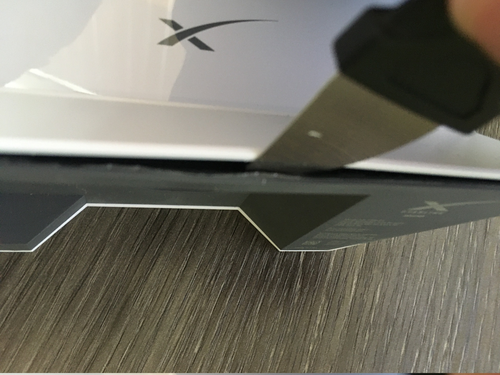
 Grabbed a pair of flush cutters and wedged 'em in there.
If you find the joint between the flange and body, you can get the edge to peel away like this.
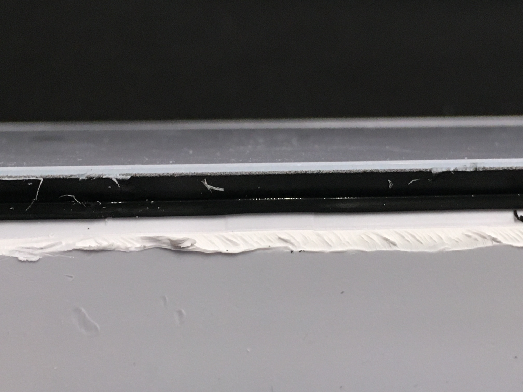
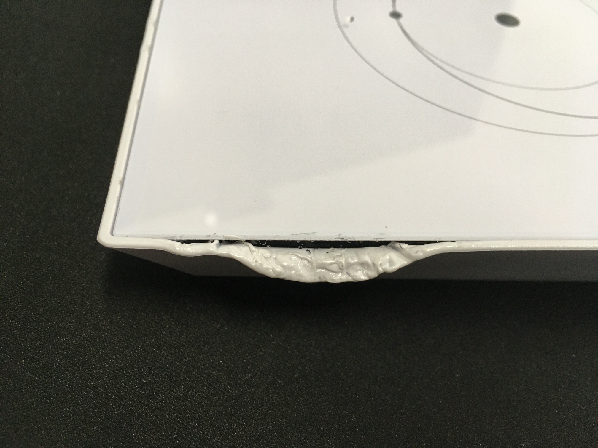
 The glue! It's a very flexable and low durometer. Bears a strong resemblance of the adhesive I've seen used to affix vehicle windshields to frames.
It's a glass panel, and Elon companies tend to do a lot of technology sharing, so it isn't a completely absurd idea that it might literally be the same stuff.
Interior
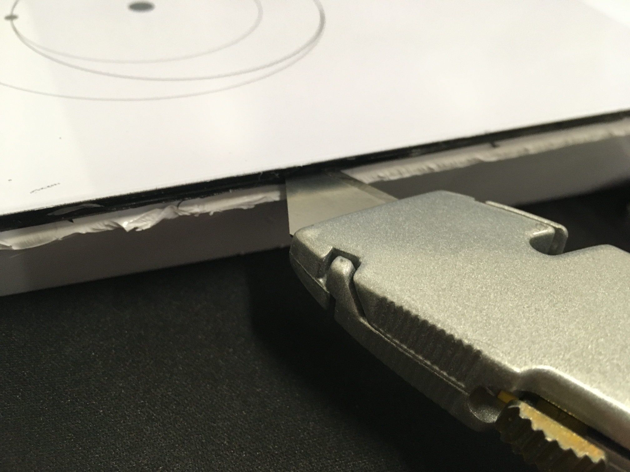
Utility knife worked great - we're in!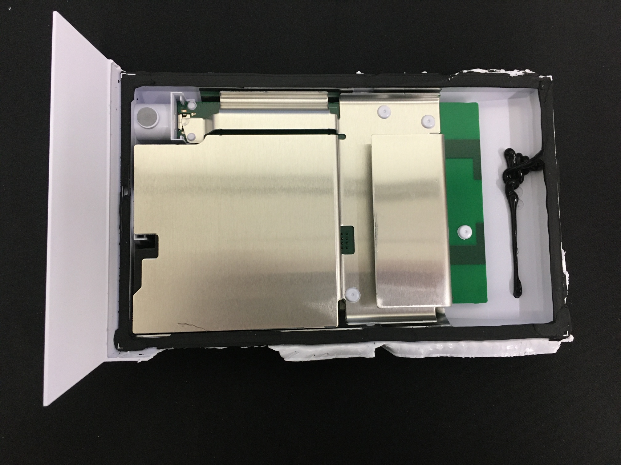 Turns out most of the weight of the router is the glass panel and metal shielding.
 That is by far the most shielding I've ever seen in any consumer/commercial-grade wireless network equipment.
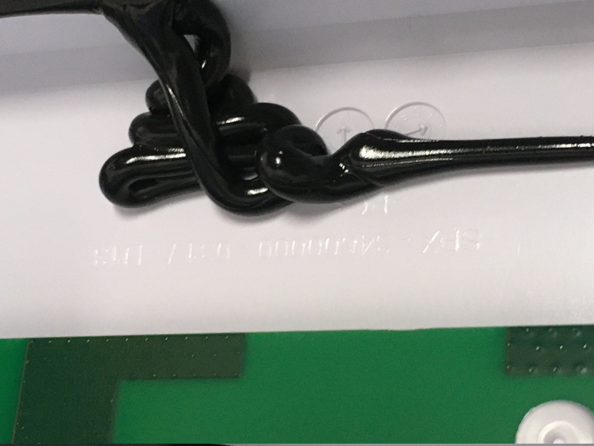
Well done, SpaceX. Check out how they grounded the front shield:
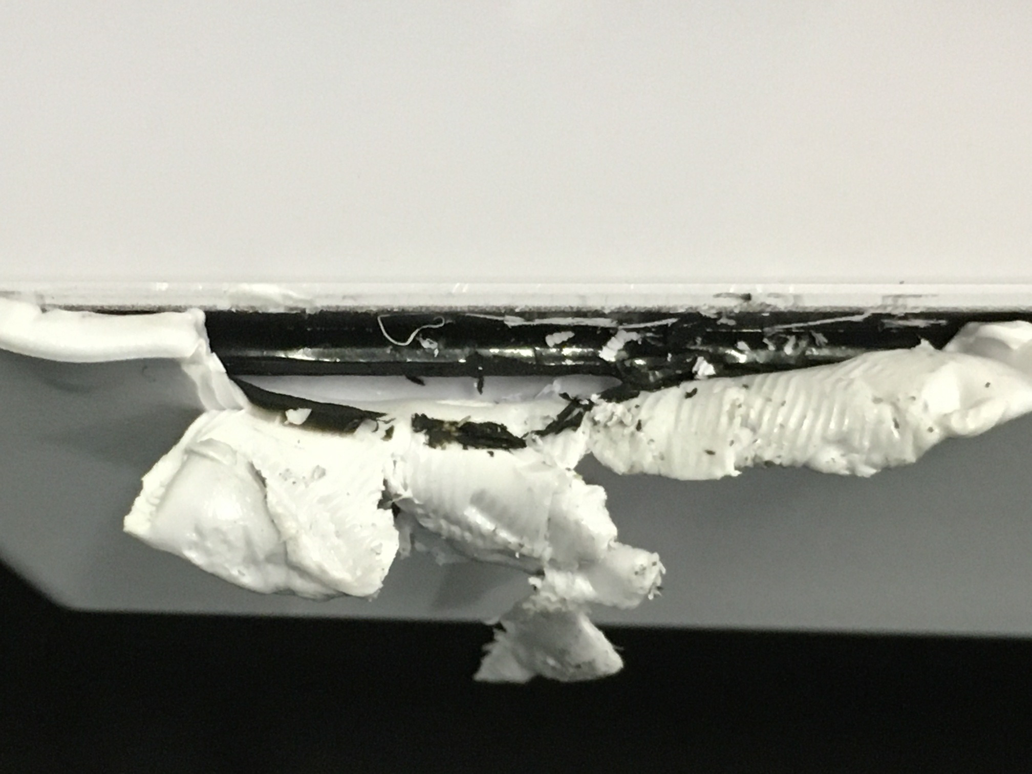
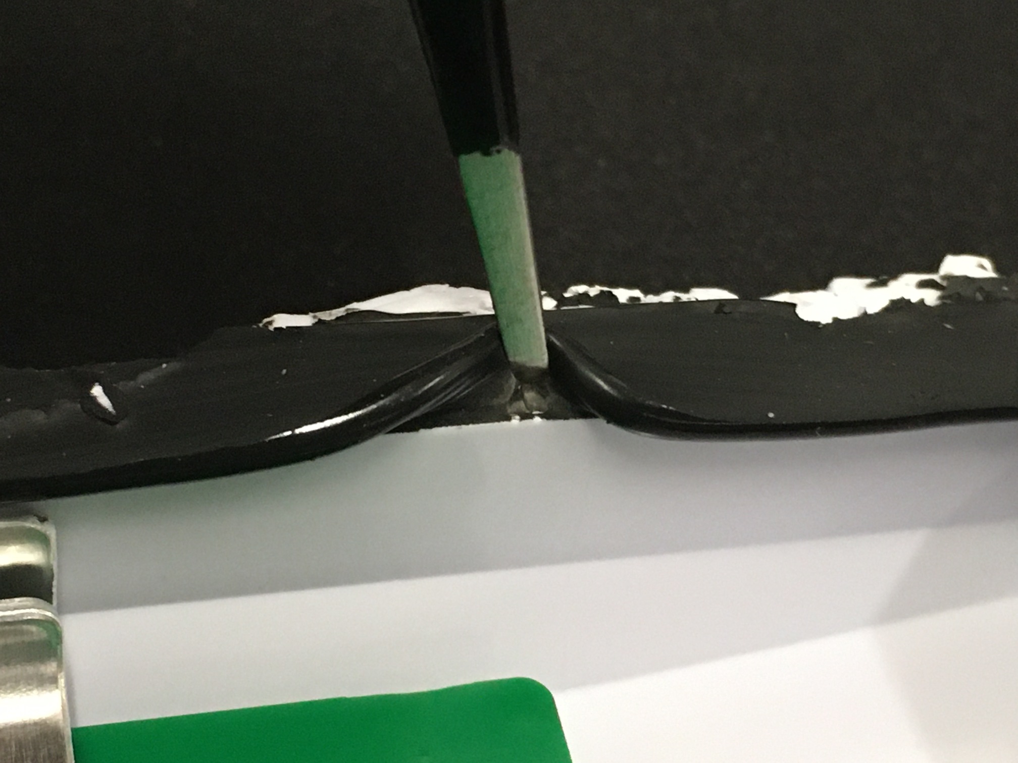
 More glue detail, plus some molding text.
 Removing the shield is easy; ten seconds with a drill and a little bit of prying.
 Finally, the electronics!
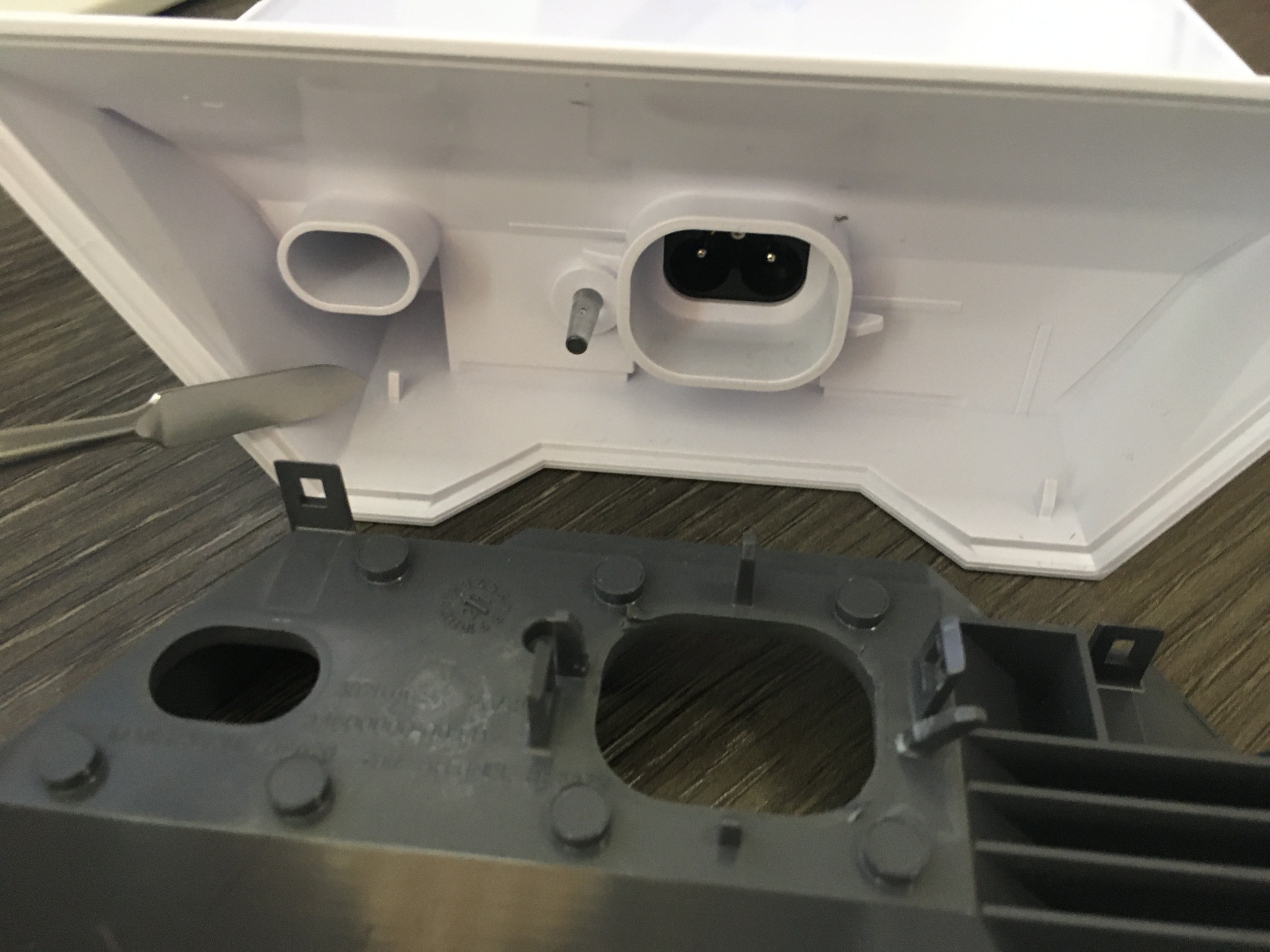
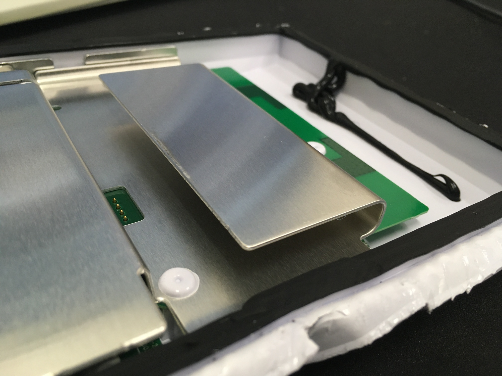
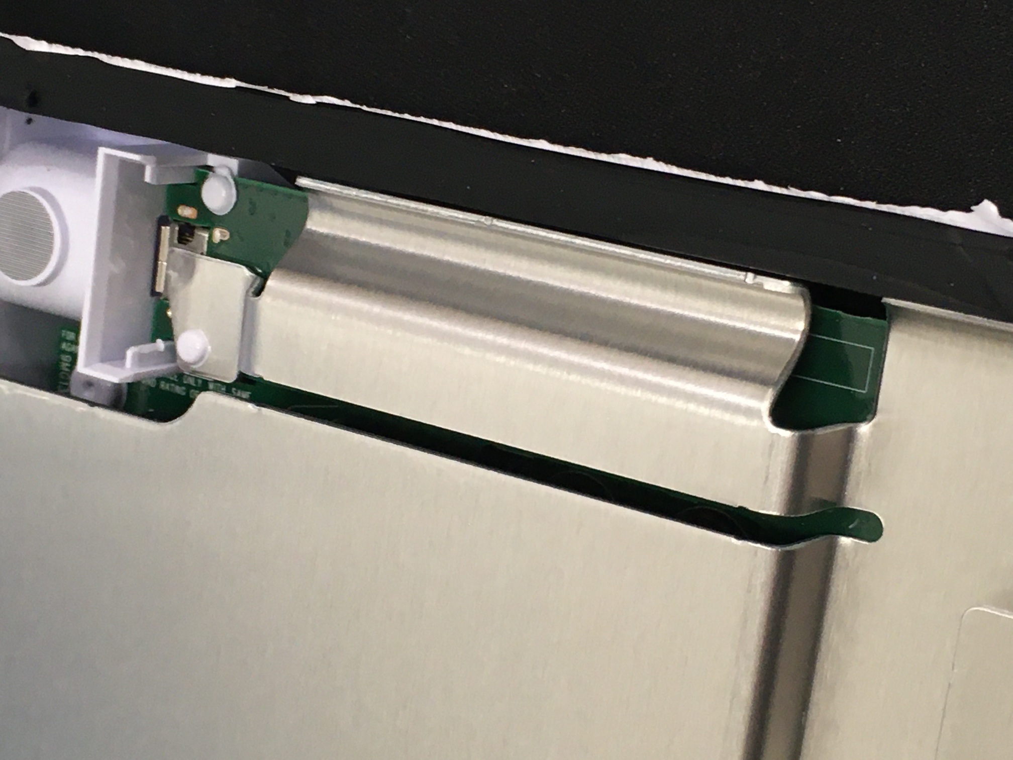
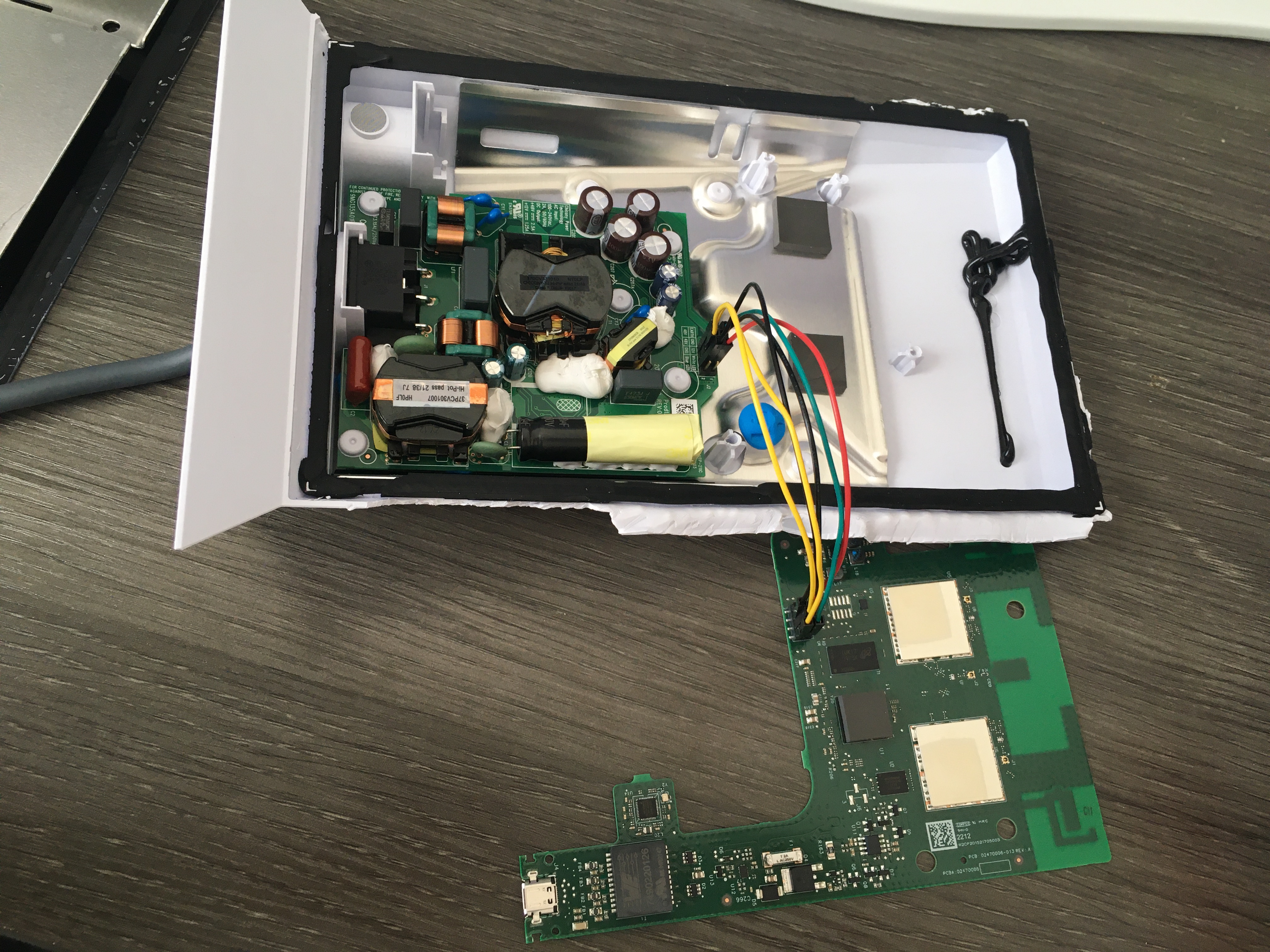
 The router has two PCBs: the antenna/radio/SoC board on top, and the power supply under that.
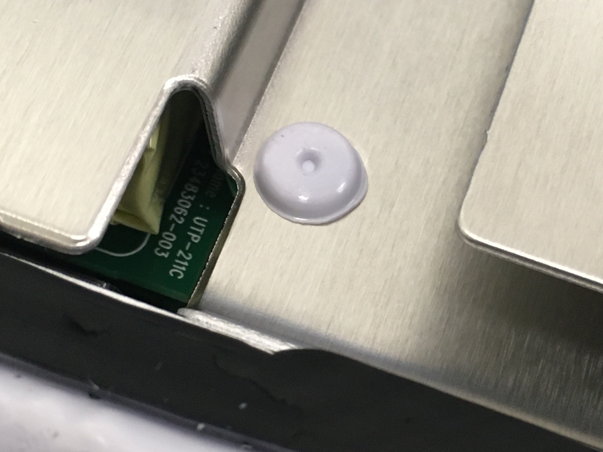
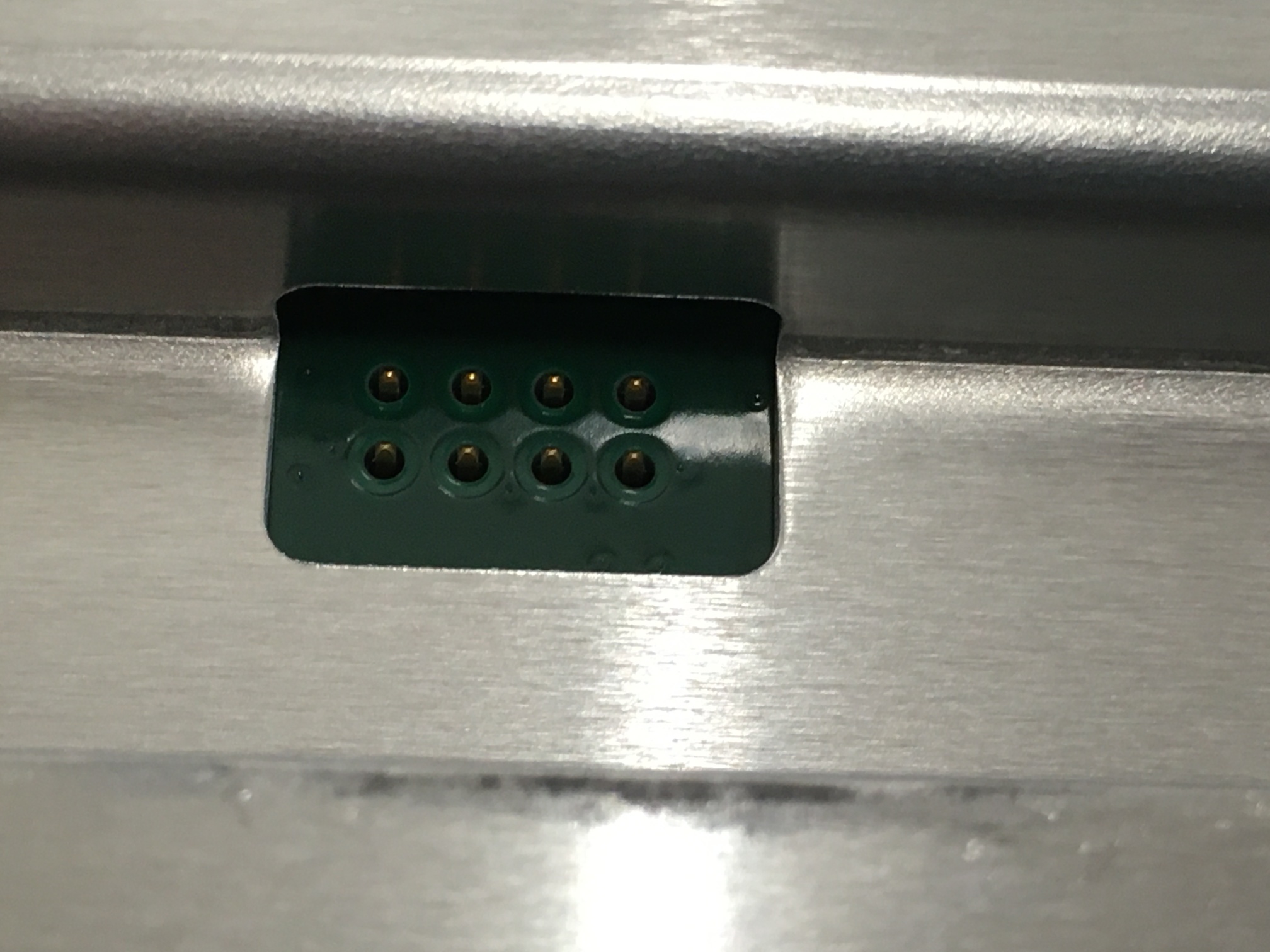
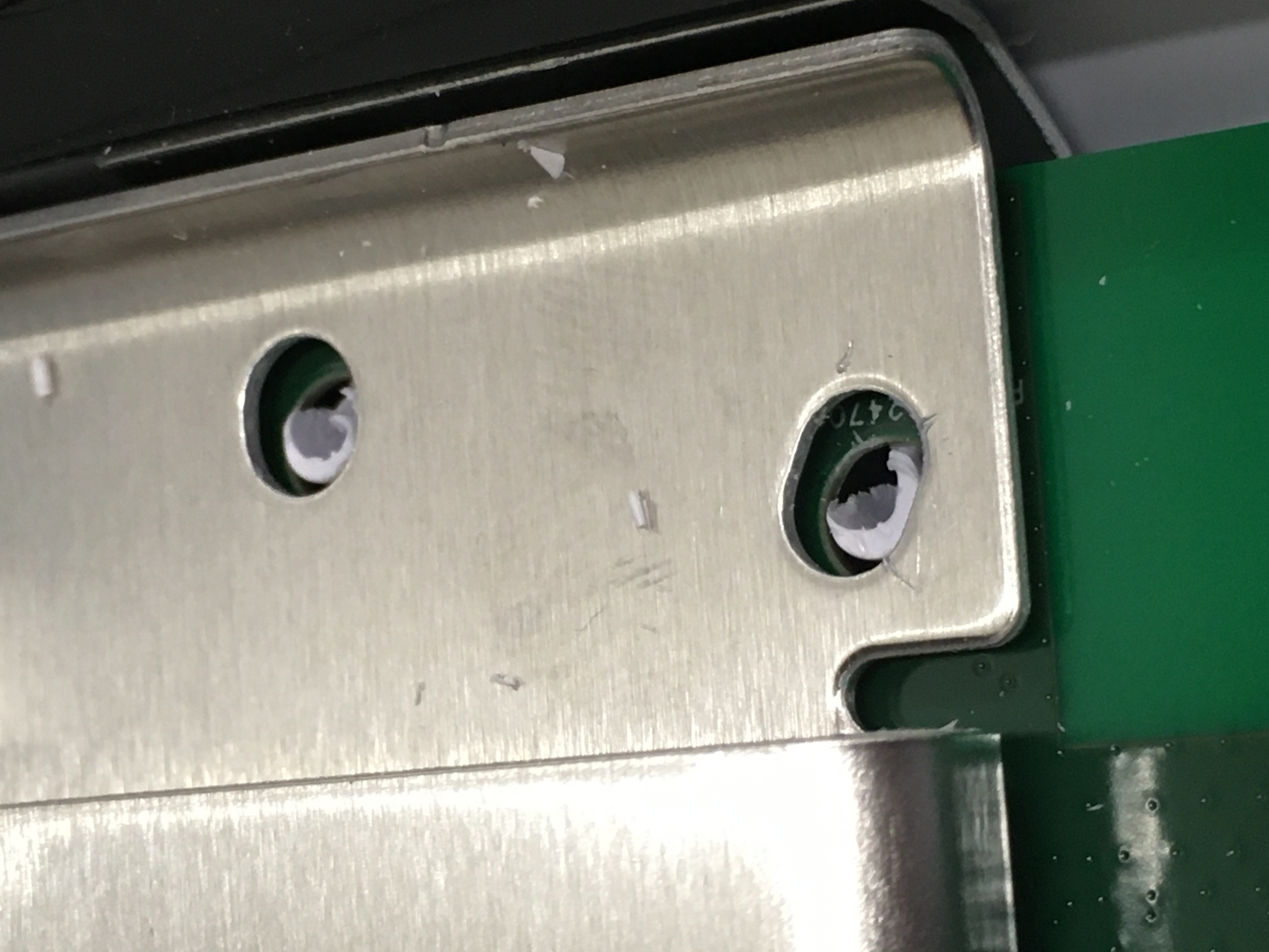
Note the thermoplastic stake in the upper left, next to the proprietary SpaceX connector - at this point, that is all that is holding down the top PCB.
WARNING: Lift the top PCB straight up! There are two little nubs next to the Dishy connector that hook around ridges in the plastic case - if you just lift and twist (like I did), one or both of these will break off!
The router has two PCBs: the antenna/radio/SoC board on top, and the power supply under that.
Note the thermoplastic stake in the upper left, next to the proprietary SpaceX connector - at this point, that is all that is holding down the top PCB.
WARNING: Lift the top PCB straight up! There are two little nubs next to the Dishy connector that hook around ridges in the plastic case - if you just lift and twist (like I did), one or both of these will break off!
Power Supply
Some detail shots before I take the SoC board out: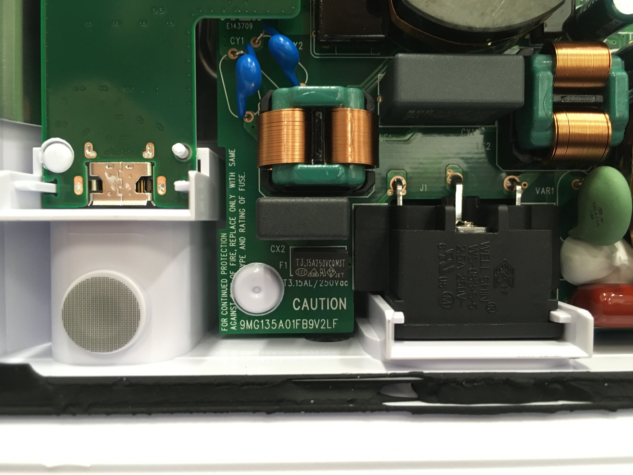
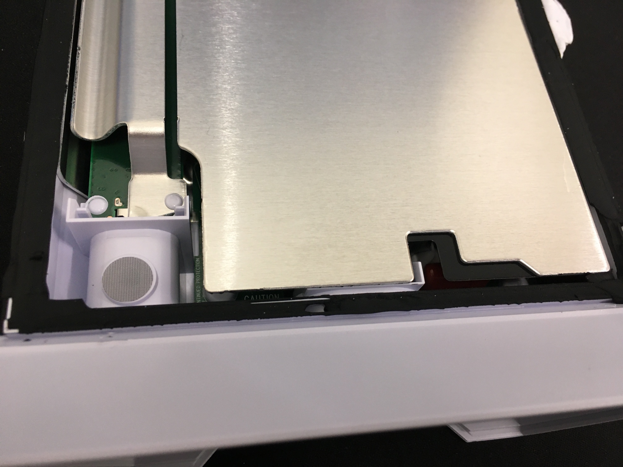
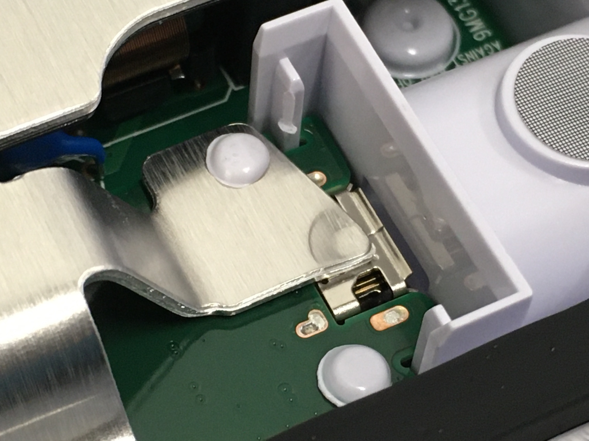
 There is exactly one connector btween the power supply PCB to the SoC board.
(Remember those LED's I talked about earlier? White = Sun, blue = Earth?)
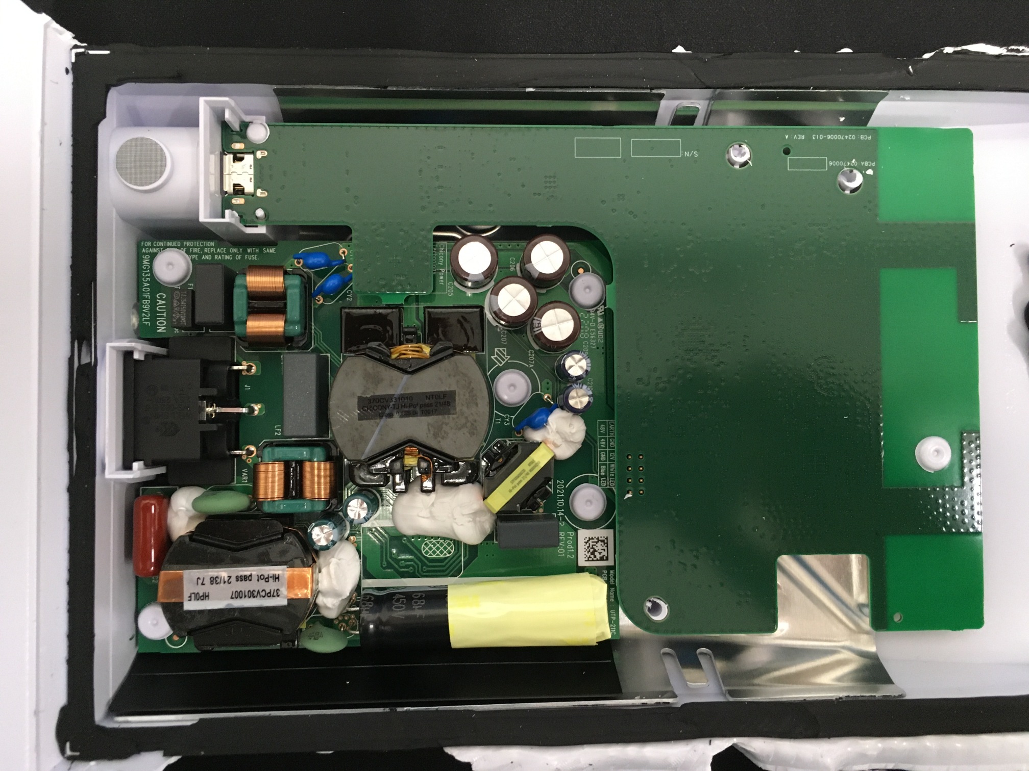
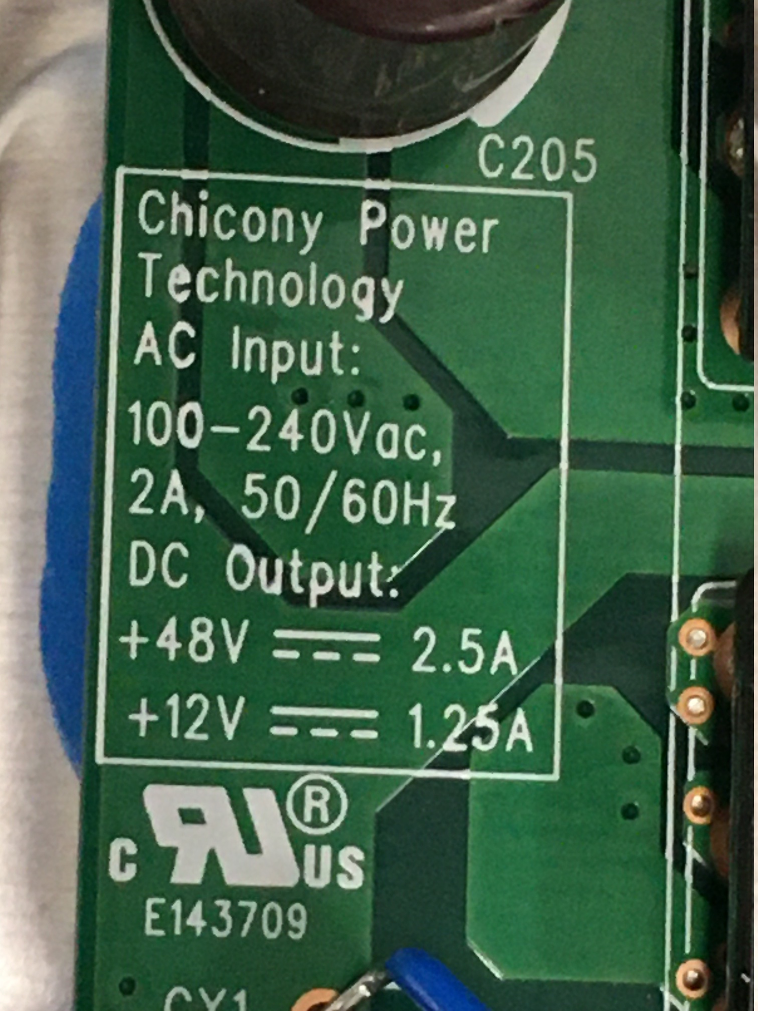
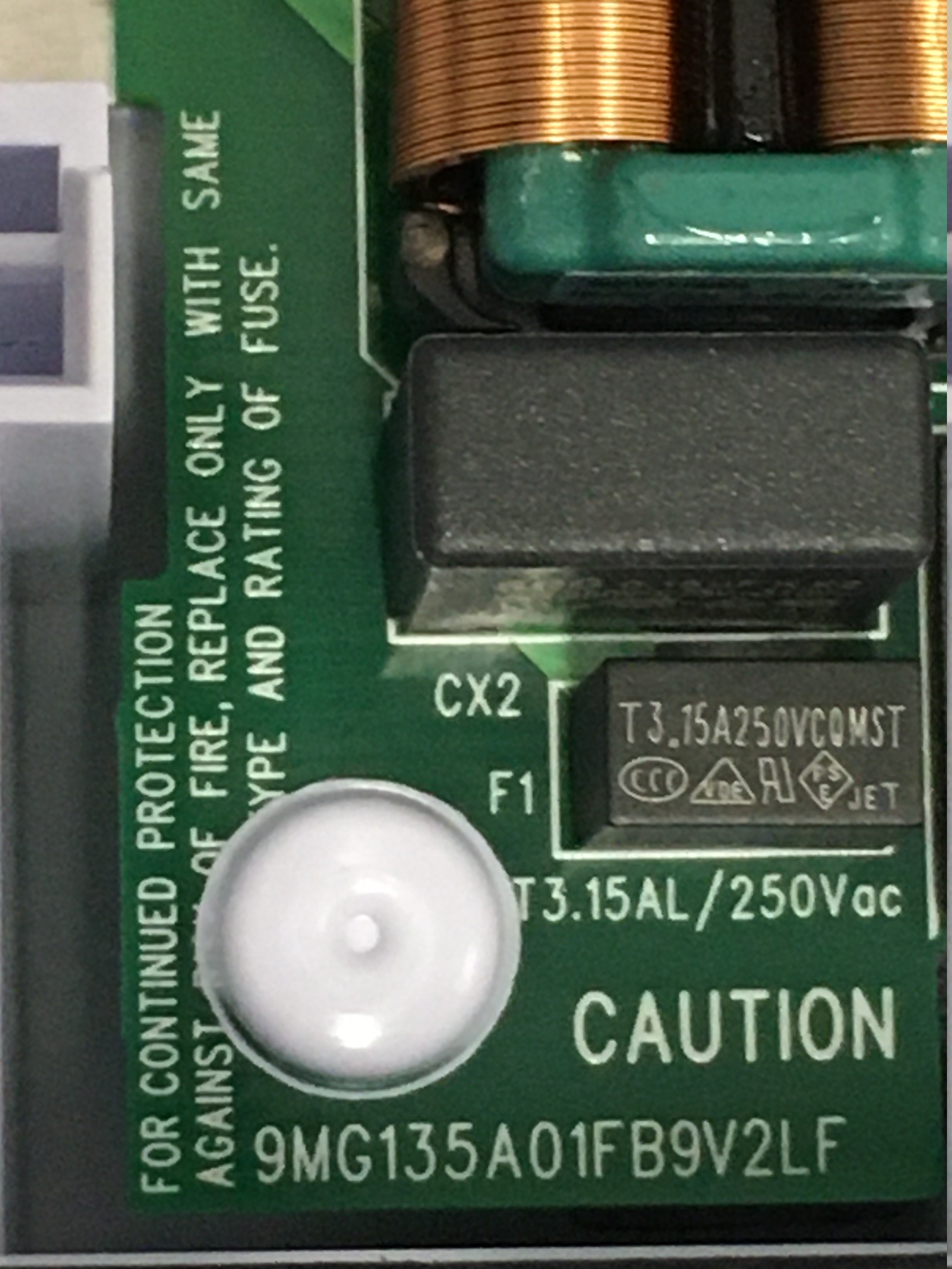
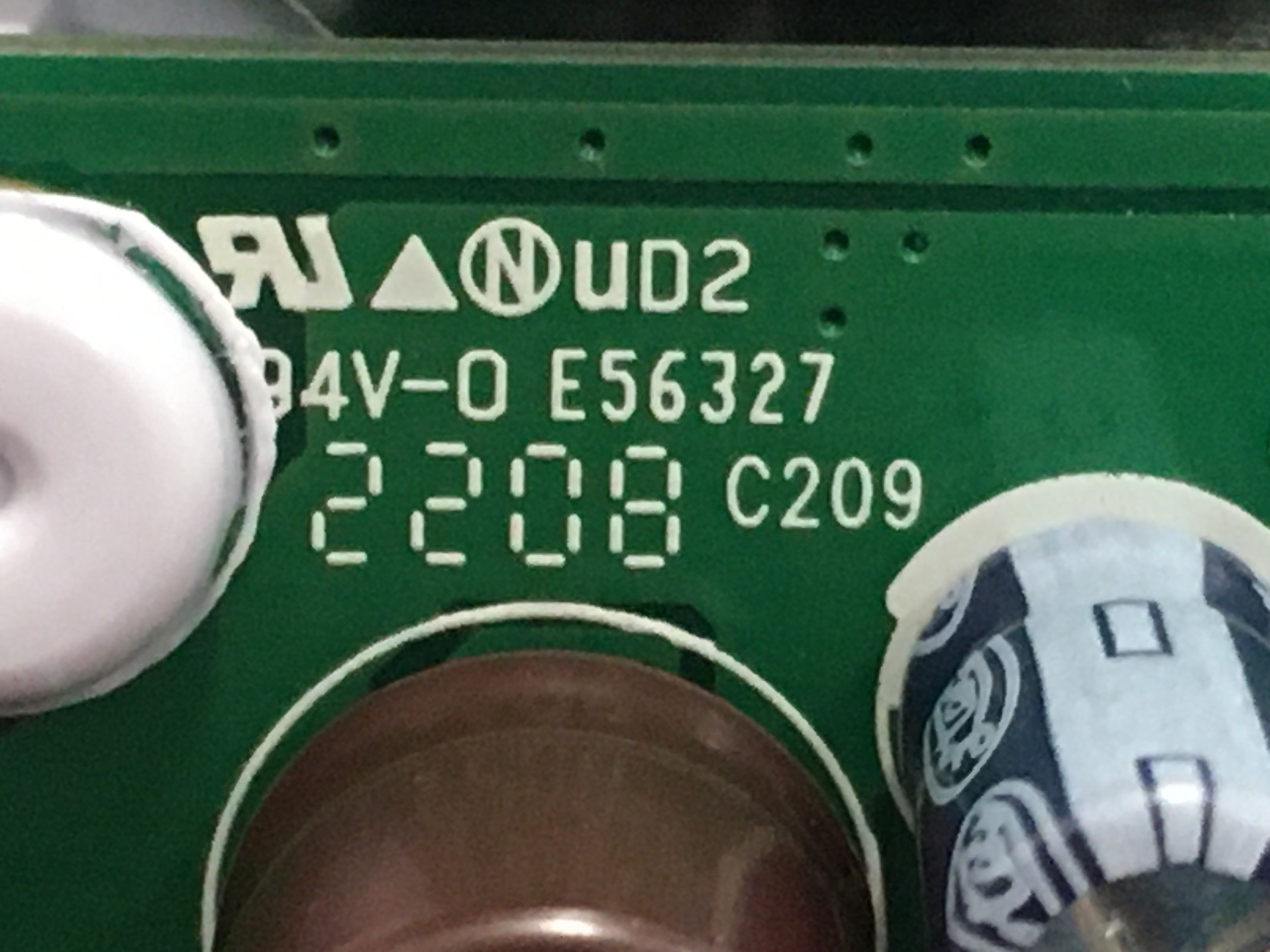
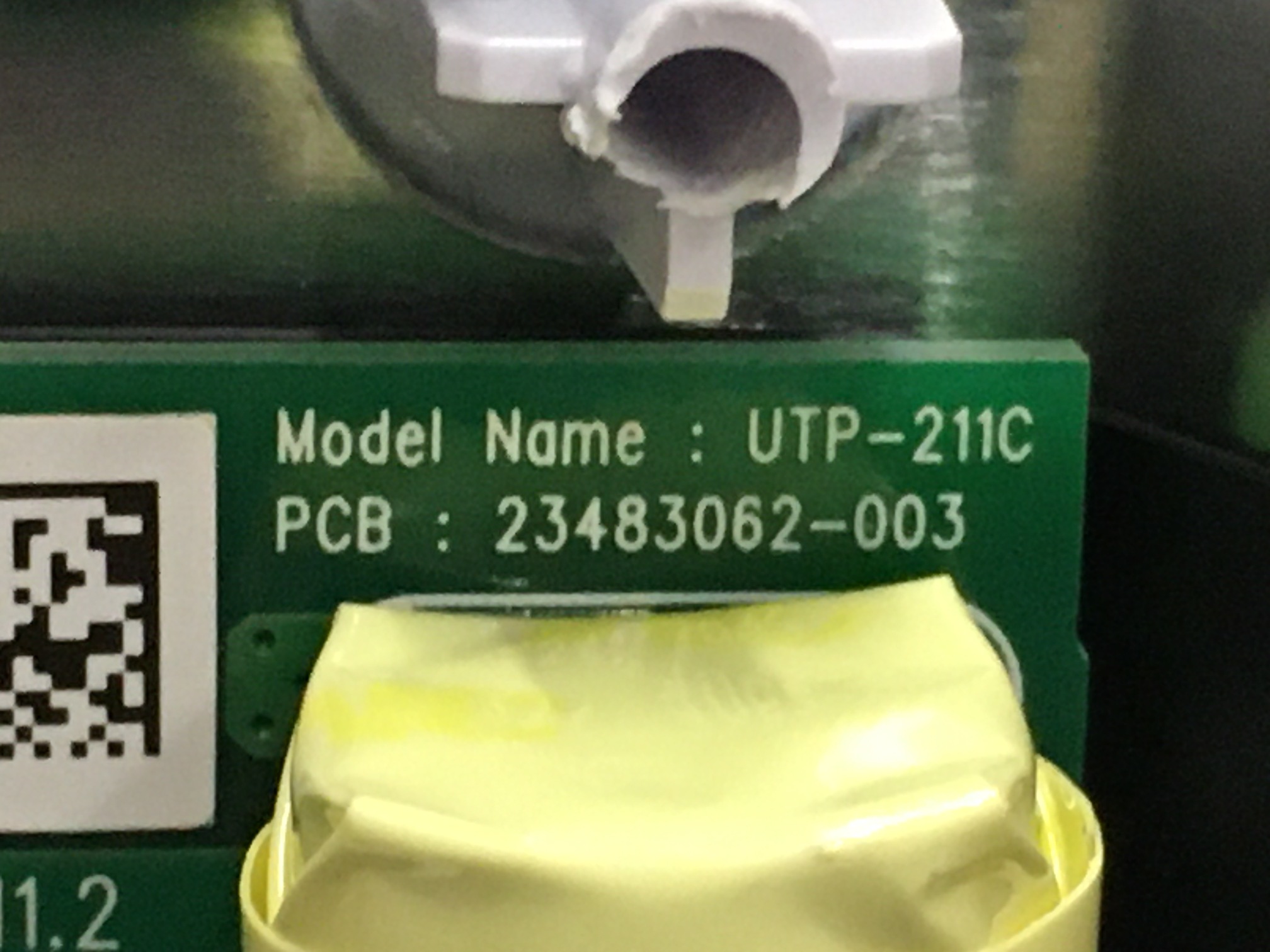
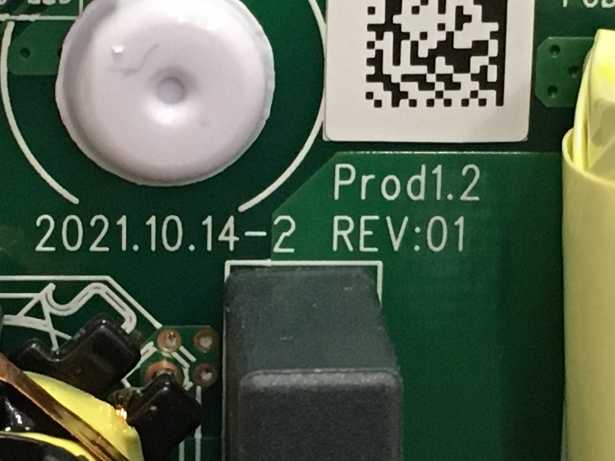
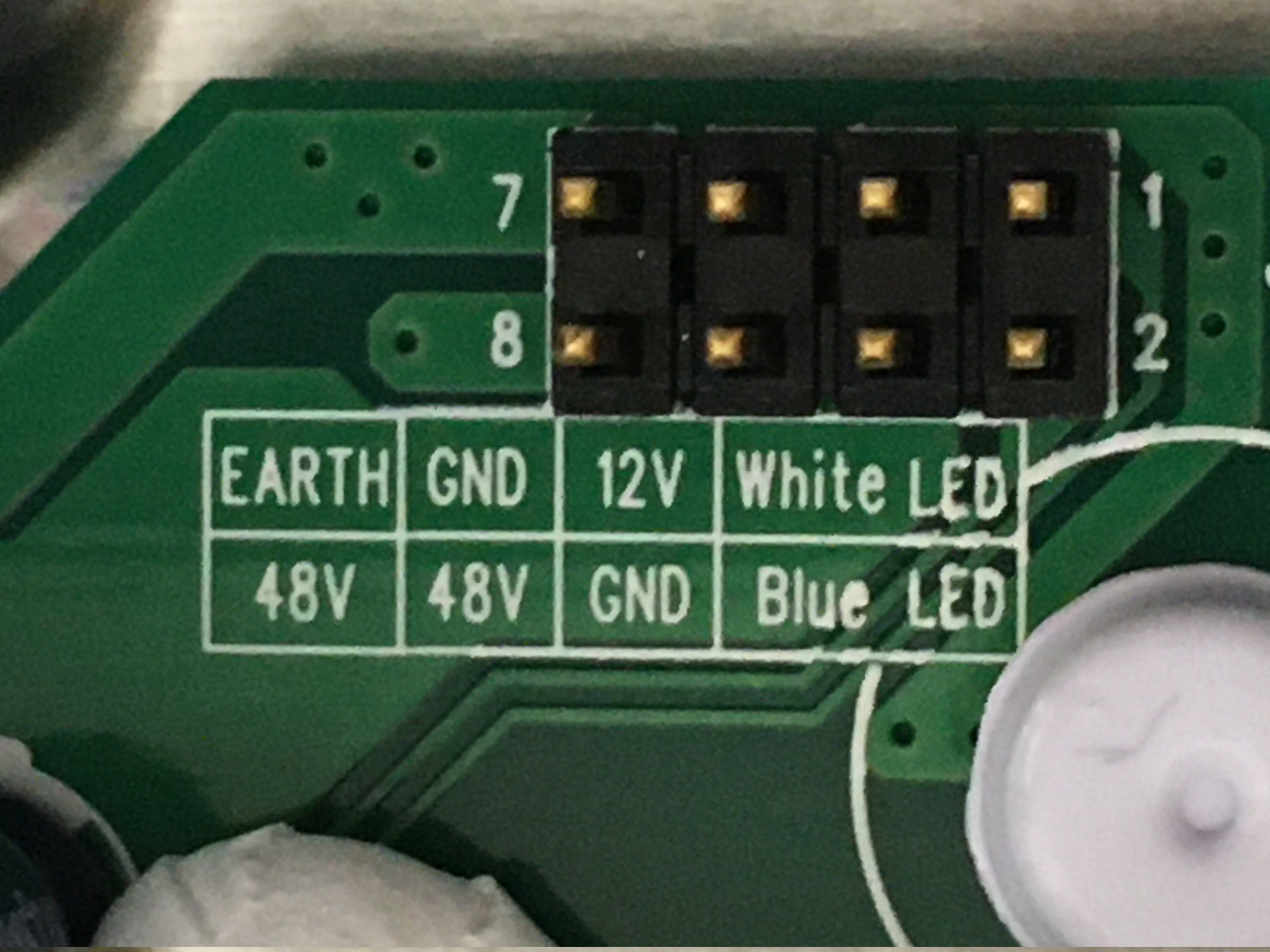 Photos of the labels that are now visible with the SoC board off:
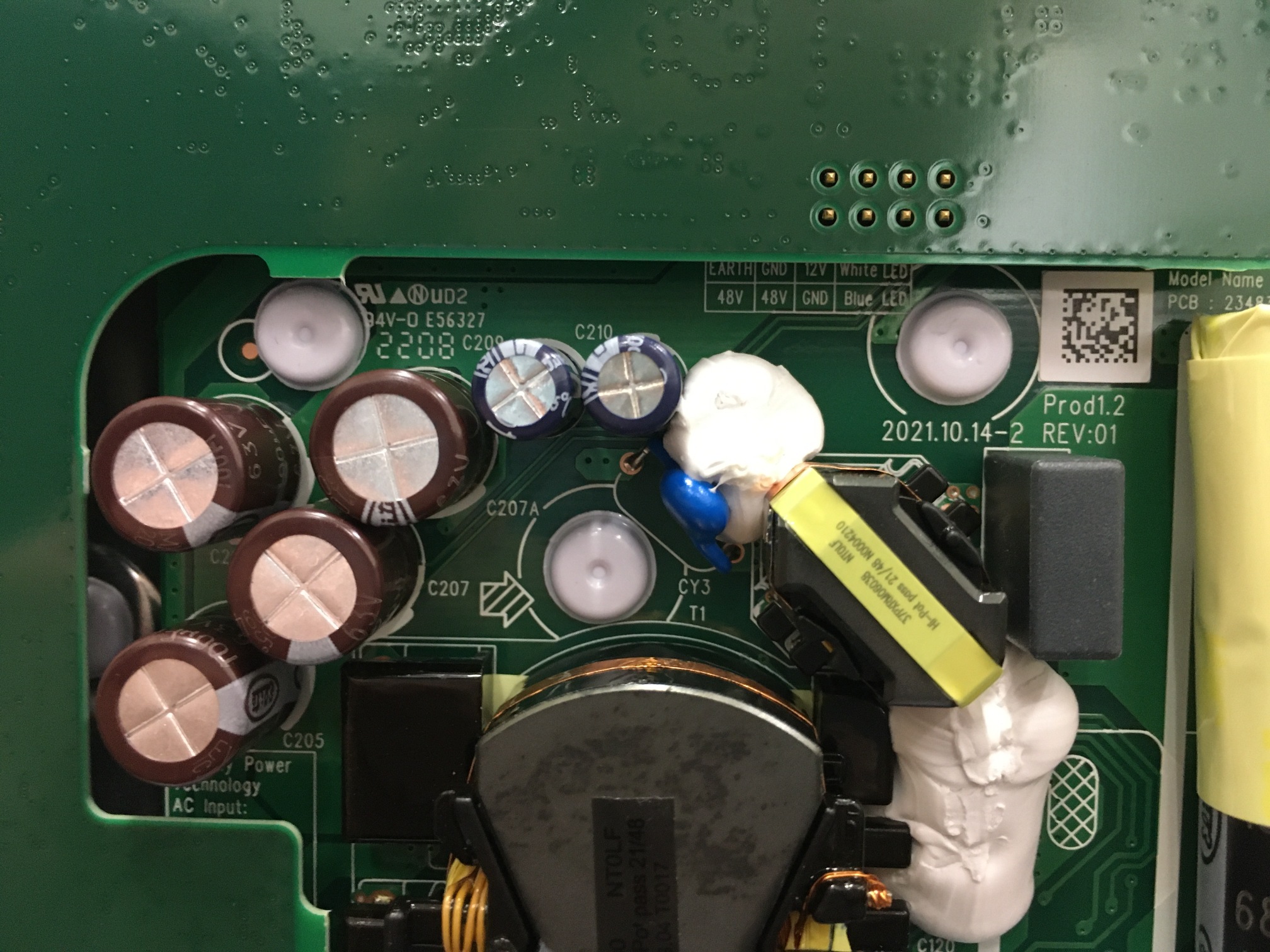
	Chicony Power Technology
	AC Input: 100-240Vac, 2A, 50/60Hz
	DC Output: +48V 2.5A, +12V 1.25A

	F1 : T3.15L/250Vac

	9MG135A01FB9V2LF

	Model Name : router
	PCB : 23483062-003

	2021.10.14-2

	Prod1.2
	REV:01
SoC Board
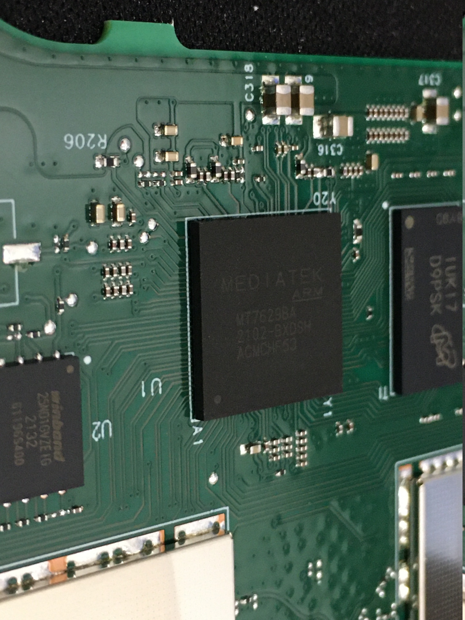
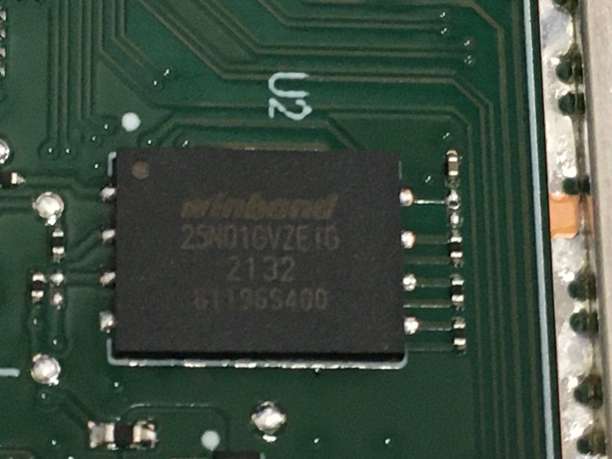
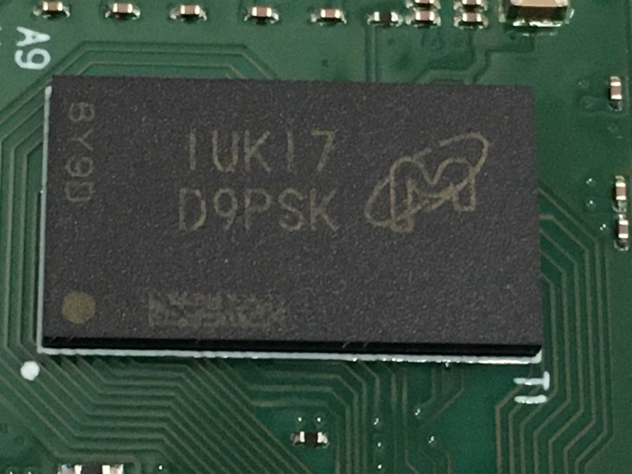
And what about the SoC board?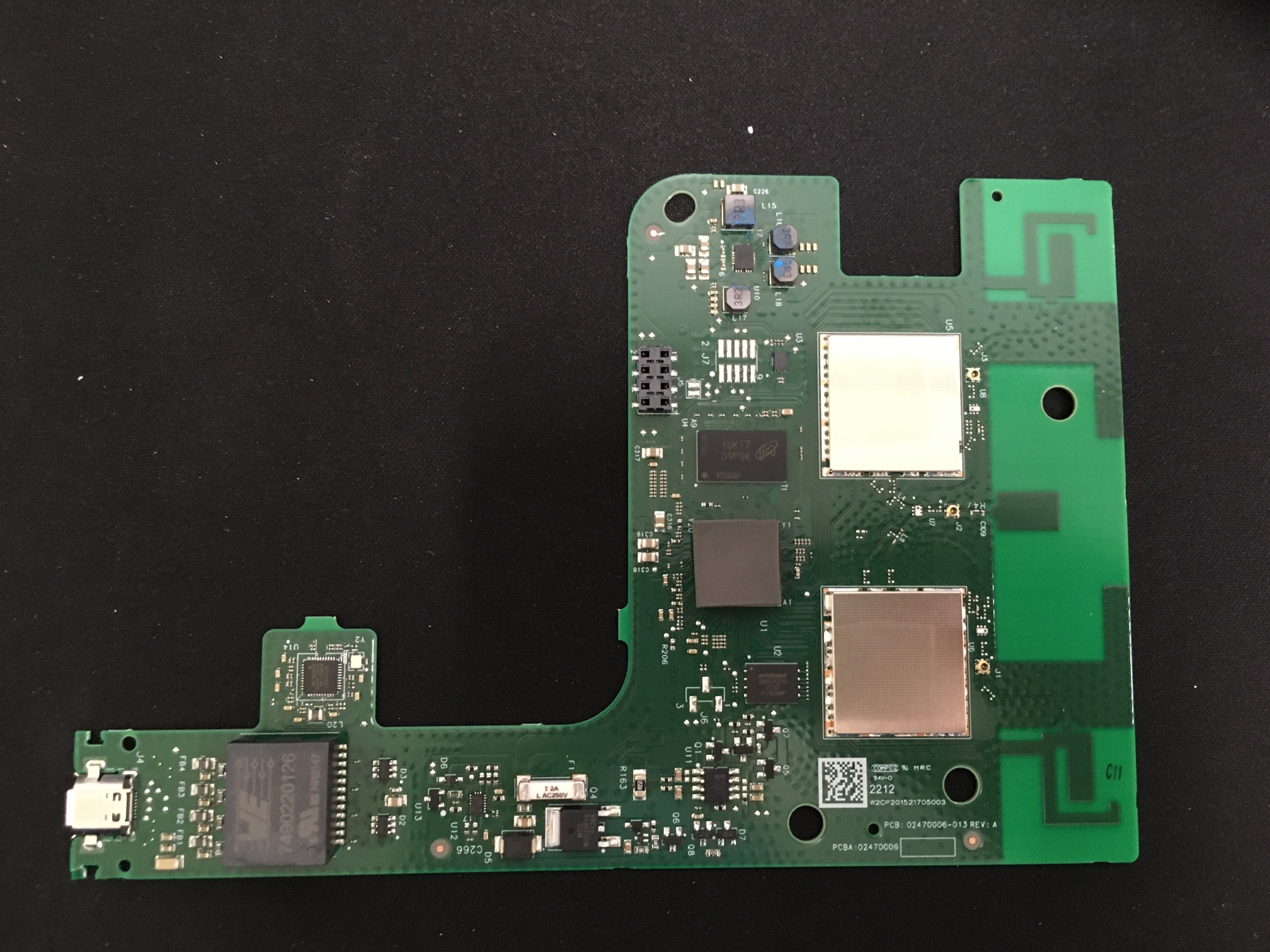 It's carrying a Mediatek MT76298A SoC, 1 Gbit NAND flash (Windbond 25N01GVZEIG, aka W25N01GVZEIG), and presumably DRAM from Micron (1UK17 D9PSK).
 All the parts had thermal pads between them and the front shield.
The Ethernet electronics are pretty interesting. Most of the reason I opened this was to establish a ground-truth of how SpaceX implemented Power over Ethernet for Dishy.
All the parts had thermal pads between them and the front shield.
The Ethernet electronics are pretty interesting. Most of the reason I opened this was to establish a ground-truth of how SpaceX implemented Power over Ethernet for Dishy.
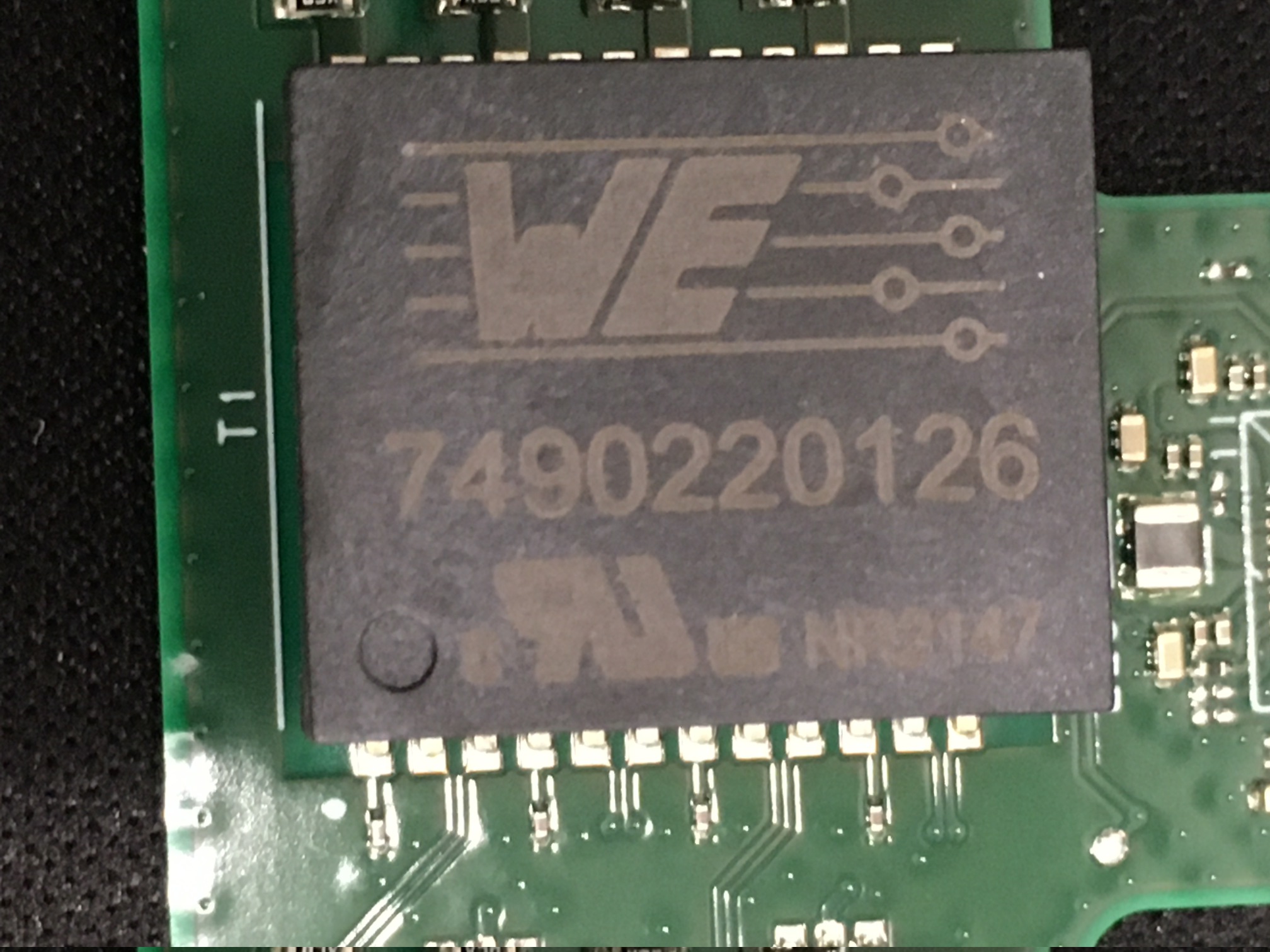
 That's a Würth Elektronik 7490220126 Ethernet transformer - oddly unlisted on their website. Custom part?
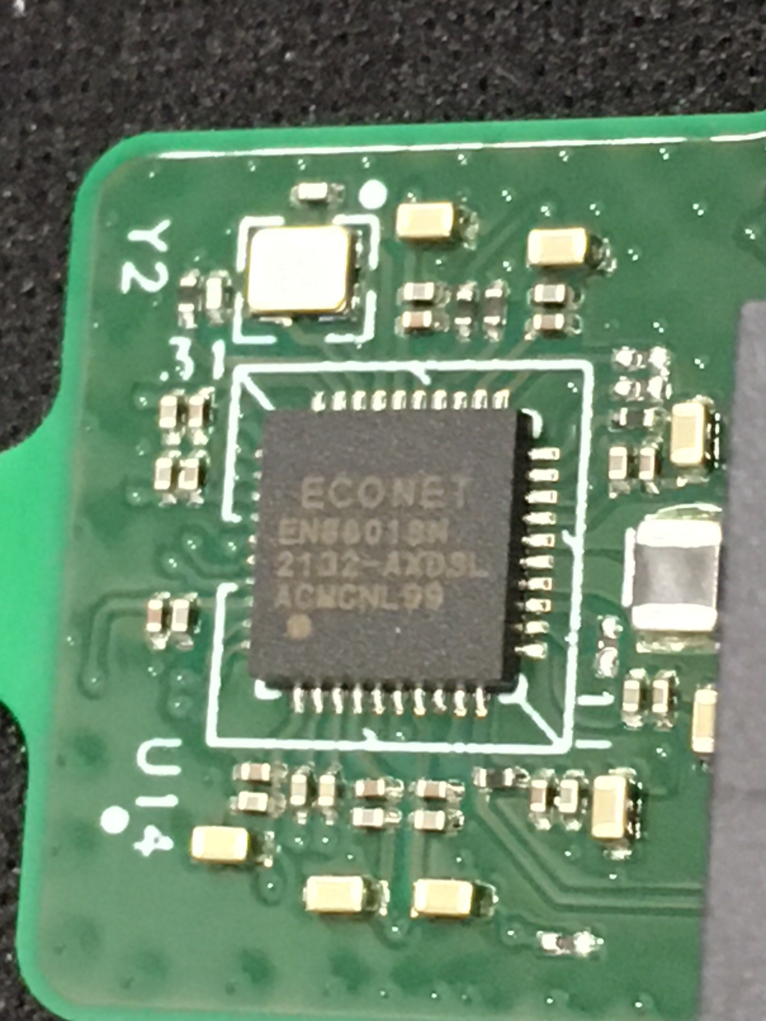
That Econet chip is a mystery - need a better photo of the part number.
That's a Würth Elektronik 7490220126 Ethernet transformer - oddly unlisted on their website. Custom part?
That Econet chip is a mystery - need a better photo of the part number.The AXDSL text is odd and probably a red herring - AFAIK the Starlink router doesn't implement or support any DSL service!
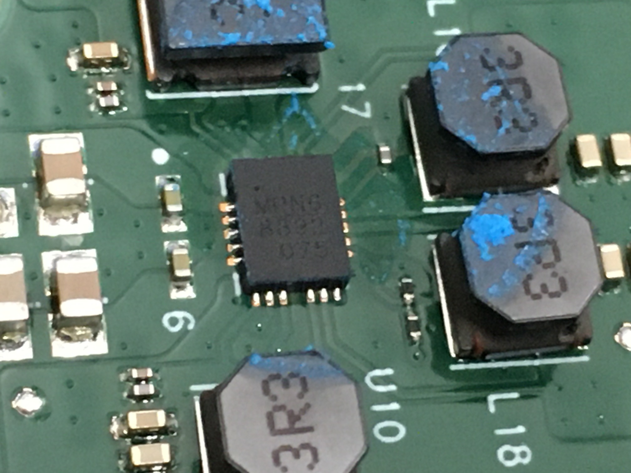
My best guess is this is an Ethernet switch chip - three ports, one to the SoC, one to Dishy, and one to the optional Ethernet port box accessory. And then this part, which is probably some kind DC DC converter - had a weird blue blob on it:
 Need to break out the needle probes and poke around a bit.
So that's the teardown. Maybe more in-depth analysis in the future? Maybe I'll even plug it in to see if it still works.
Need to break out the needle probes and poke around a bit.
So that's the teardown. Maybe more in-depth analysis in the future? Maybe I'll even plug it in to see if it still works.
Epilogue
Whaddya think? Can't even tell, right? 😂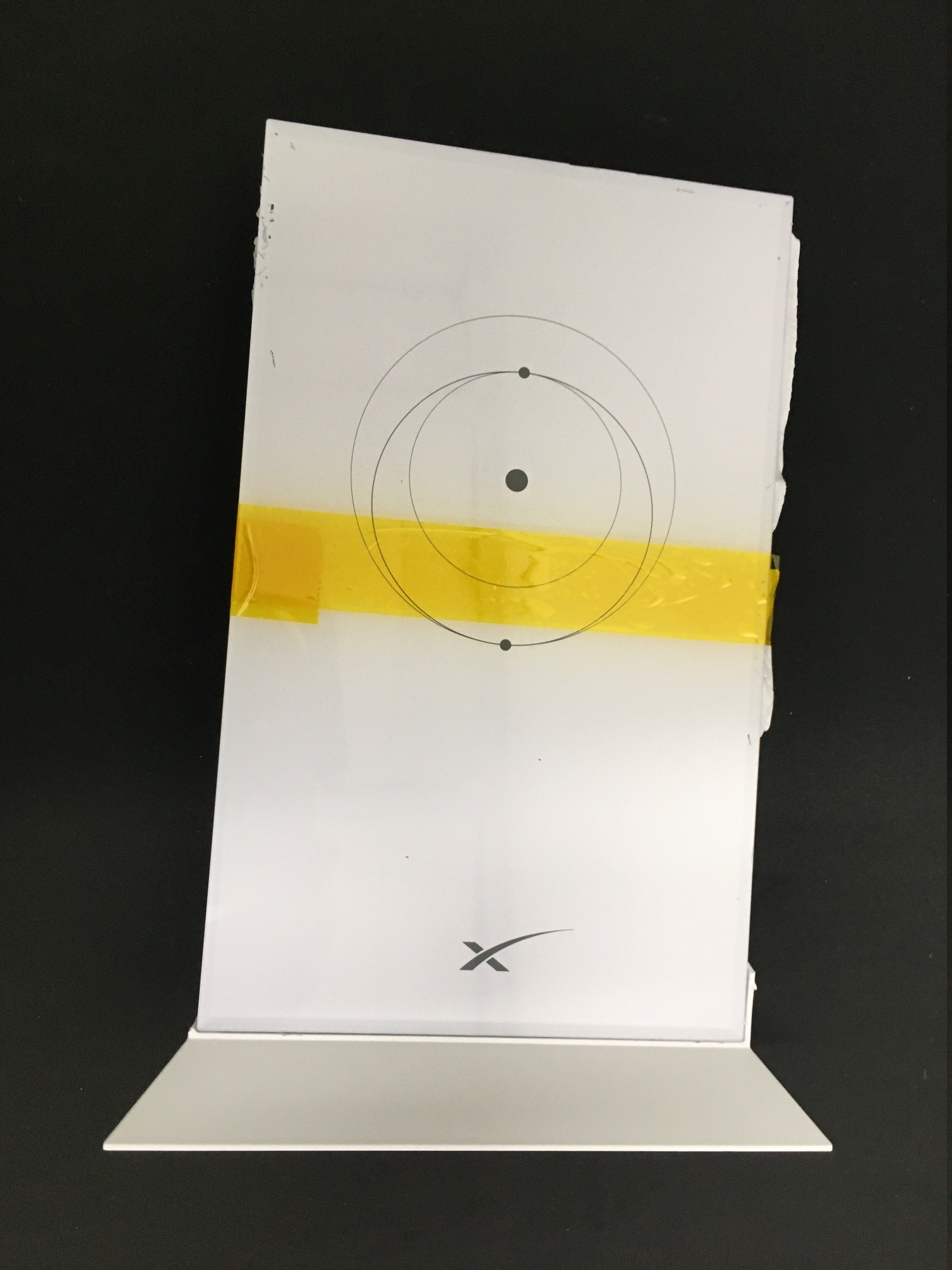
2022-05-04: Closer Look At The Electronics
One and a quarter amp through the cheapest knock-off Dupont connectors and 30 AWG wire?What's the worst that could happen?
 Nothing, surprisingly.
I only had it plugged in like this for a few minutes so I could probe for some voltages.
Only thing to note is the SoC gets warm quickly - not, like, "on fire" hot, but definitely warmer than I was expecting.
If you want to run this outside the box for any length of time, get some heat sinks. Here is a much better photo of that Econet chip:
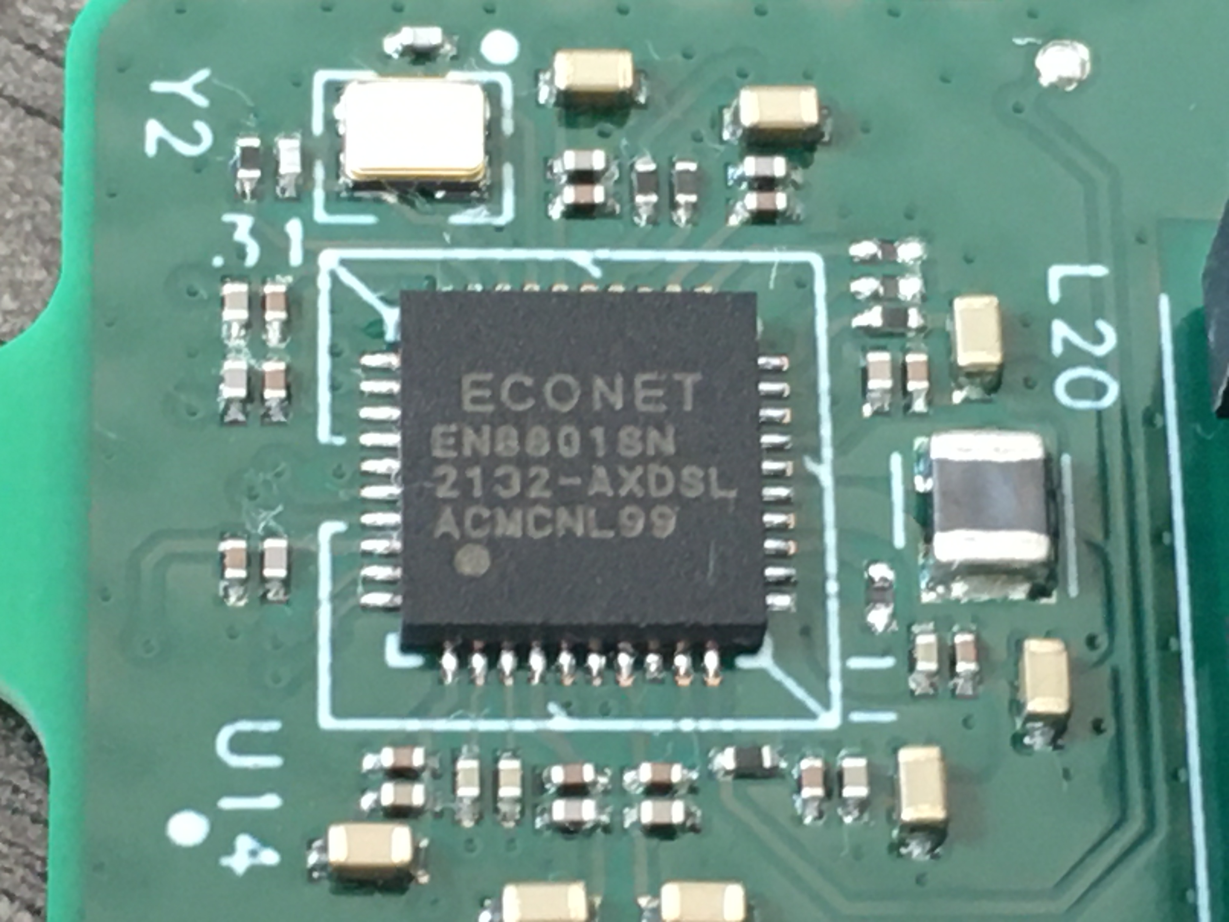 Some of the symbols are still a bit fuzzy, but this is what I think it says:
	Econet
	EN8801SN
	2132-AXDSL
	ACMCNL99
Still no joy though; not hits on the part number, and Econet is a pretty popular name - mostly environment-related IoT applications. In this case, it's not clear if Econet is a company name or an internal brand of some kind. Same deal for this chip:
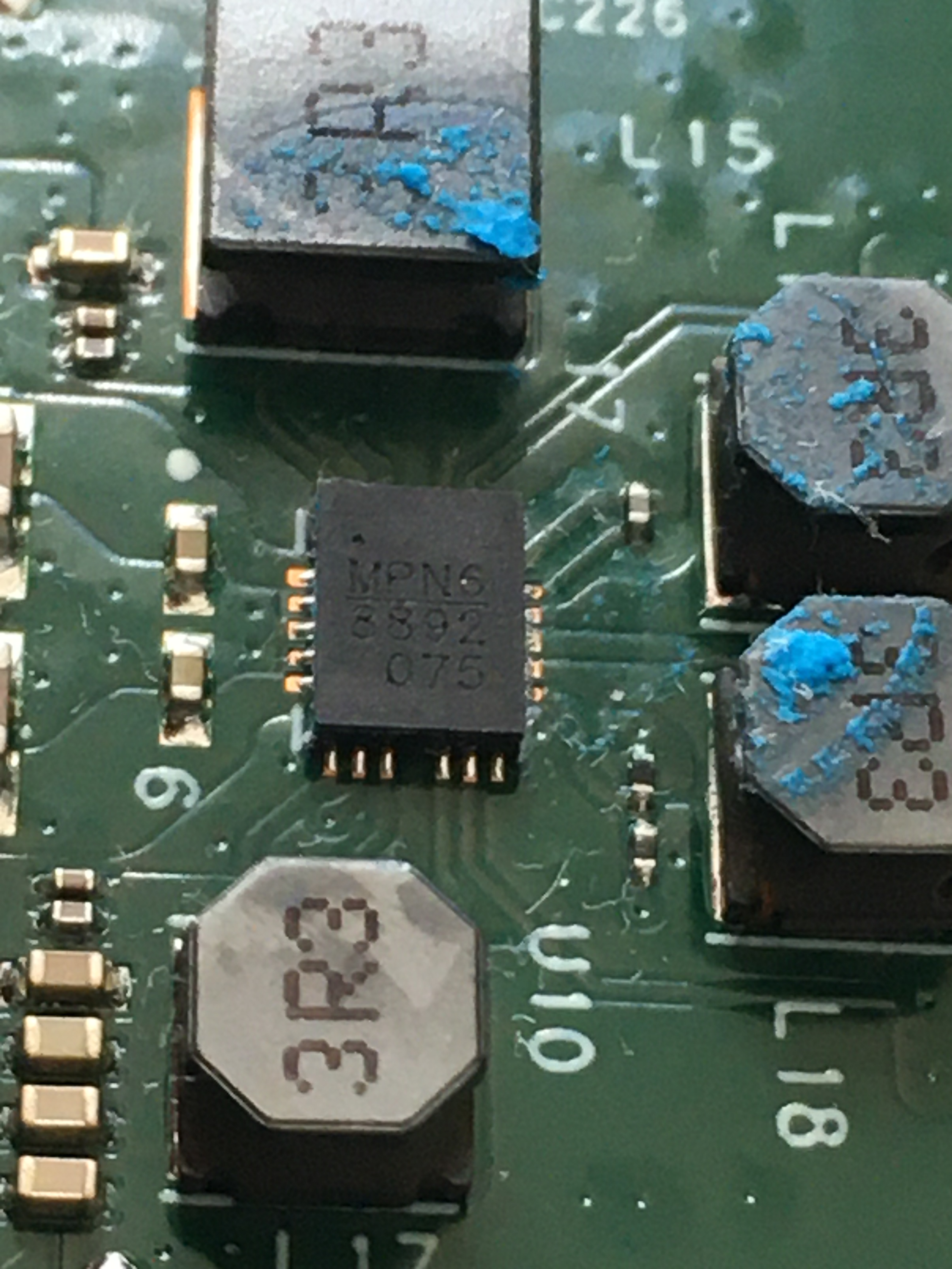
	MPN6
	8892
	075
Obviously a DC DC converter of some type, but nothing online.
The 12 V rail feeds into this cluster of parts - and only these parts, as far as I've been able to tell so far.
Wouldn't be surprised if the radios use the 12 V as well, but I assume those pads are hidden in those RF cans. Speaking of radios, there are three very tiny RF connectors on the board; J1, J2, and J3:
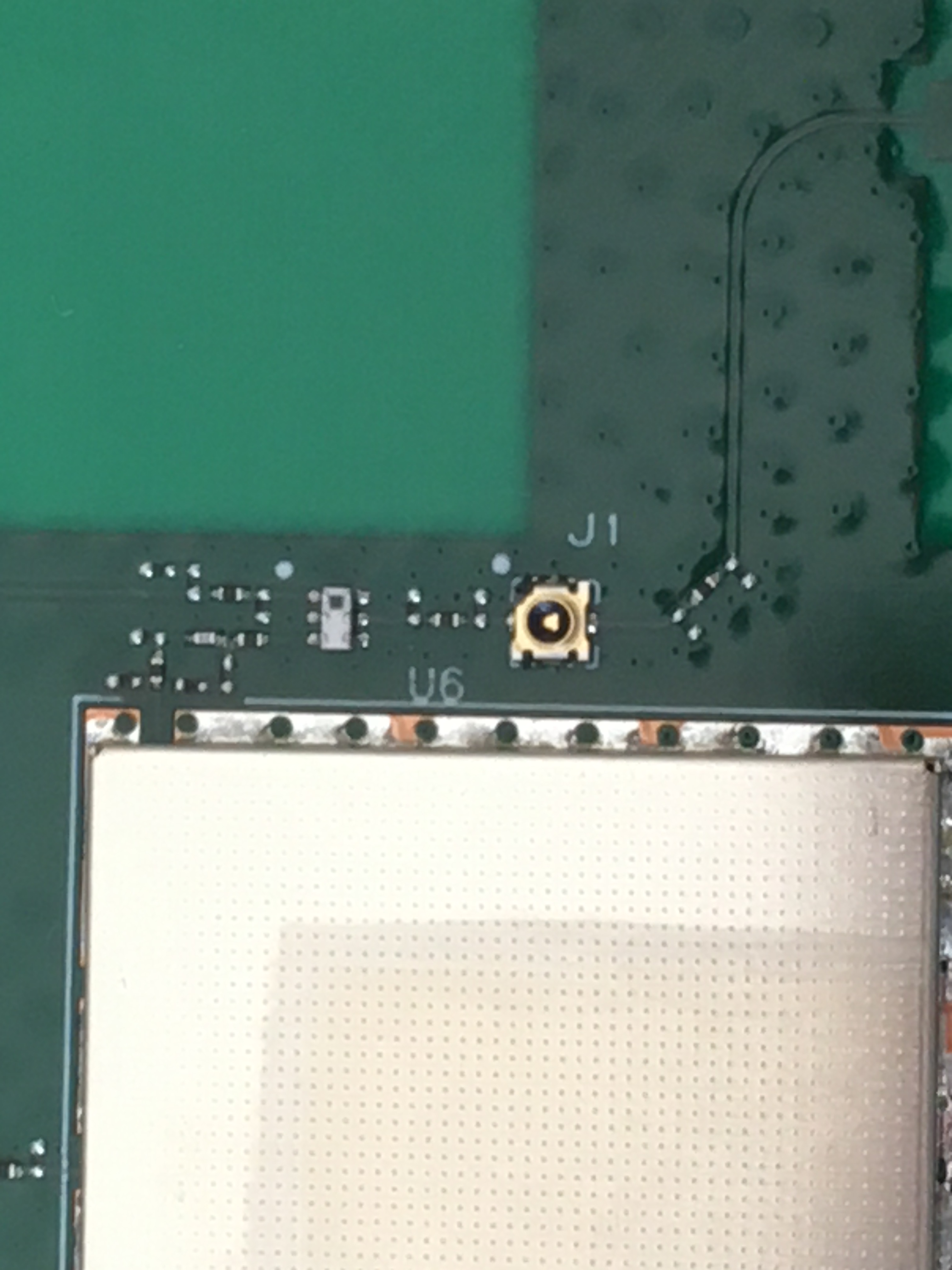
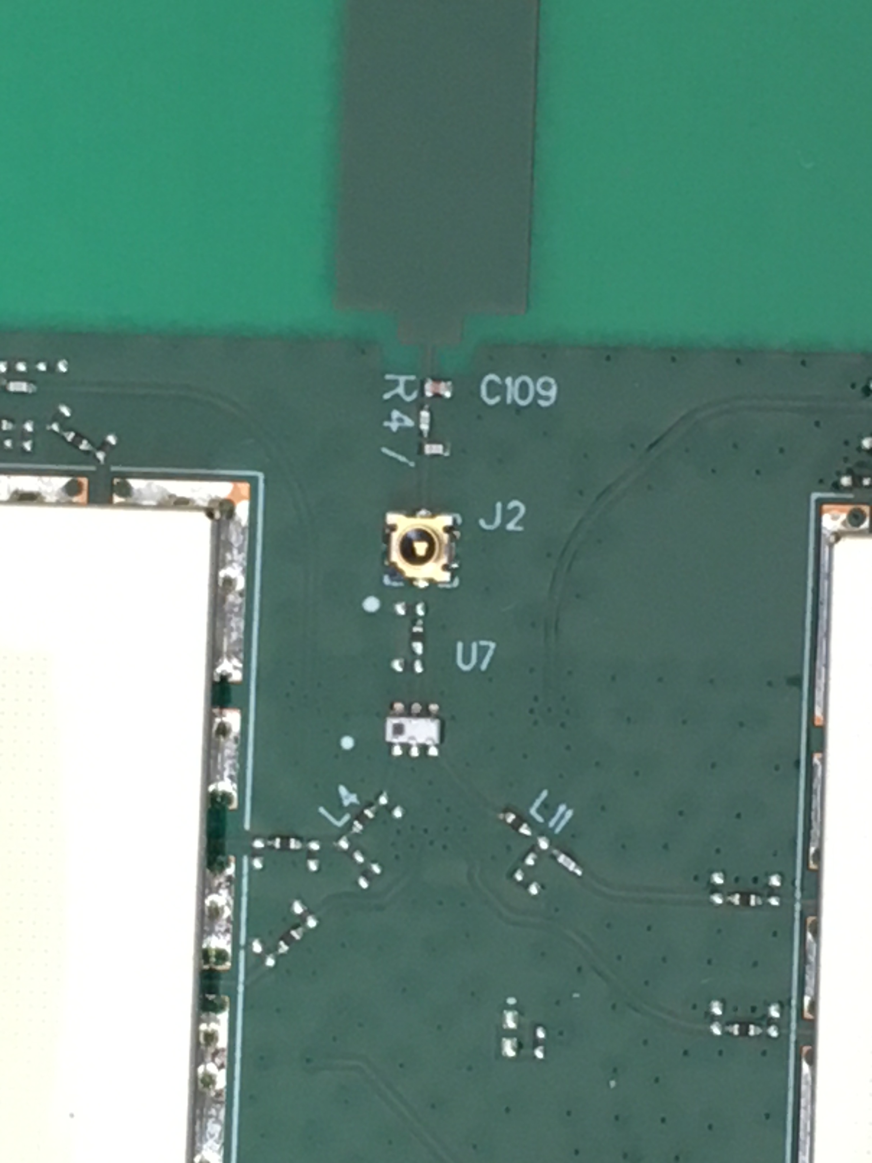
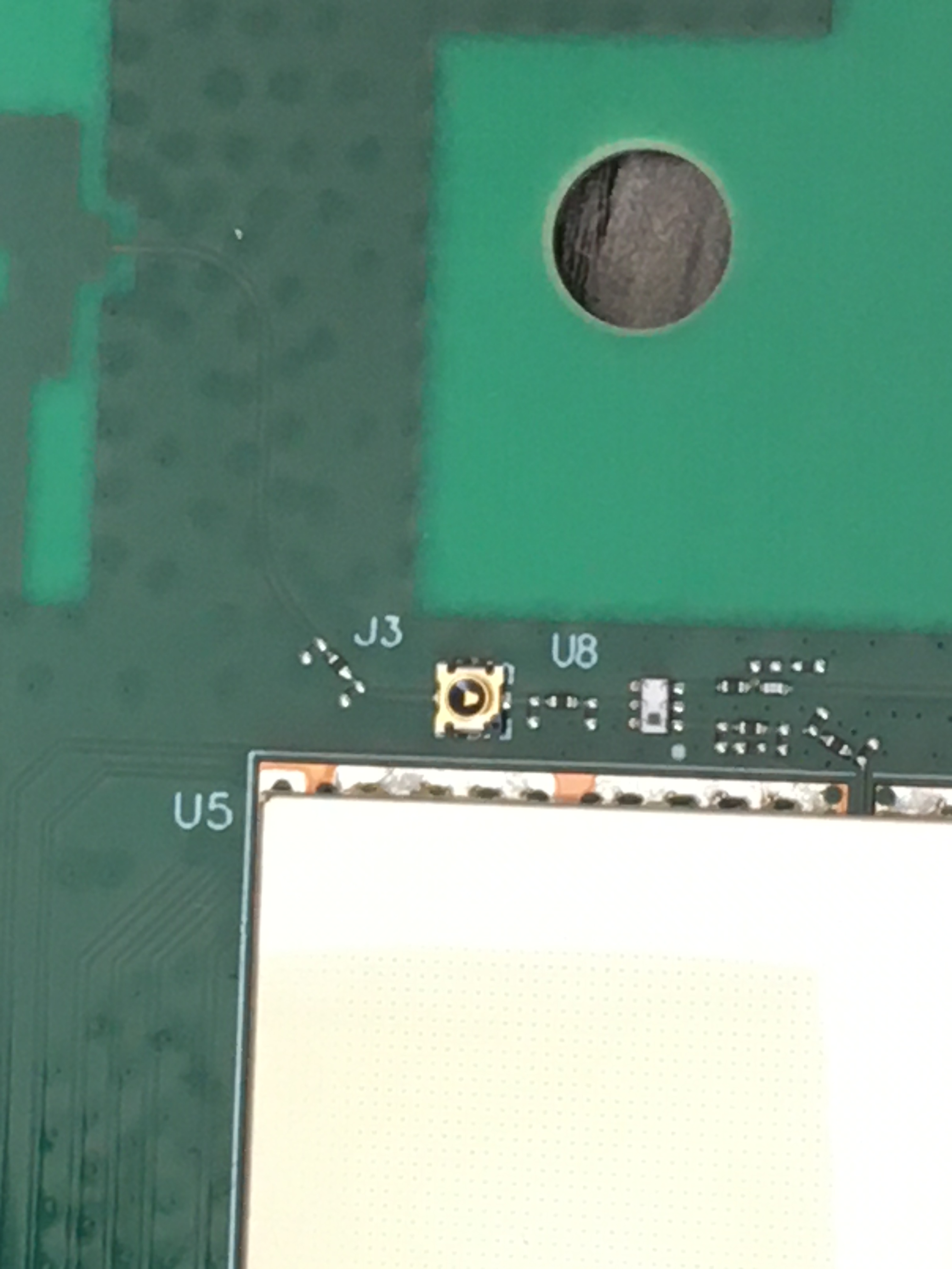 Those little white 2x3 pin parts nearby look like baluns. Connectors for extra antennas?
Now that I think about it, why are there two RF cans? Two radios? One for 5 GHz, one for 2.4 GHz? Here is a closer look at the parts and wiring next to the proprietary connector that goes to Dishy:
 The Würth Elektronik website doesn't haven't anything for the 7490220126 transformer, but if you drop the last digit (e.g. search for 749022012), you can find four parts in production today: 7490220121, 7490220122, 7490220123, 7490220124.
They're all listed as "1000 BaseT 4PPoE" parts and have exactly the same internal schematic:
The Würth Elektronik website doesn't haven't anything for the 7490220126 transformer, but if you drop the last digit (e.g. search for 749022012), you can find four parts in production today: 7490220121, 7490220122, 7490220123, 7490220124.
They're all listed as "1000 BaseT 4PPoE" parts and have exactly the same internal schematic:
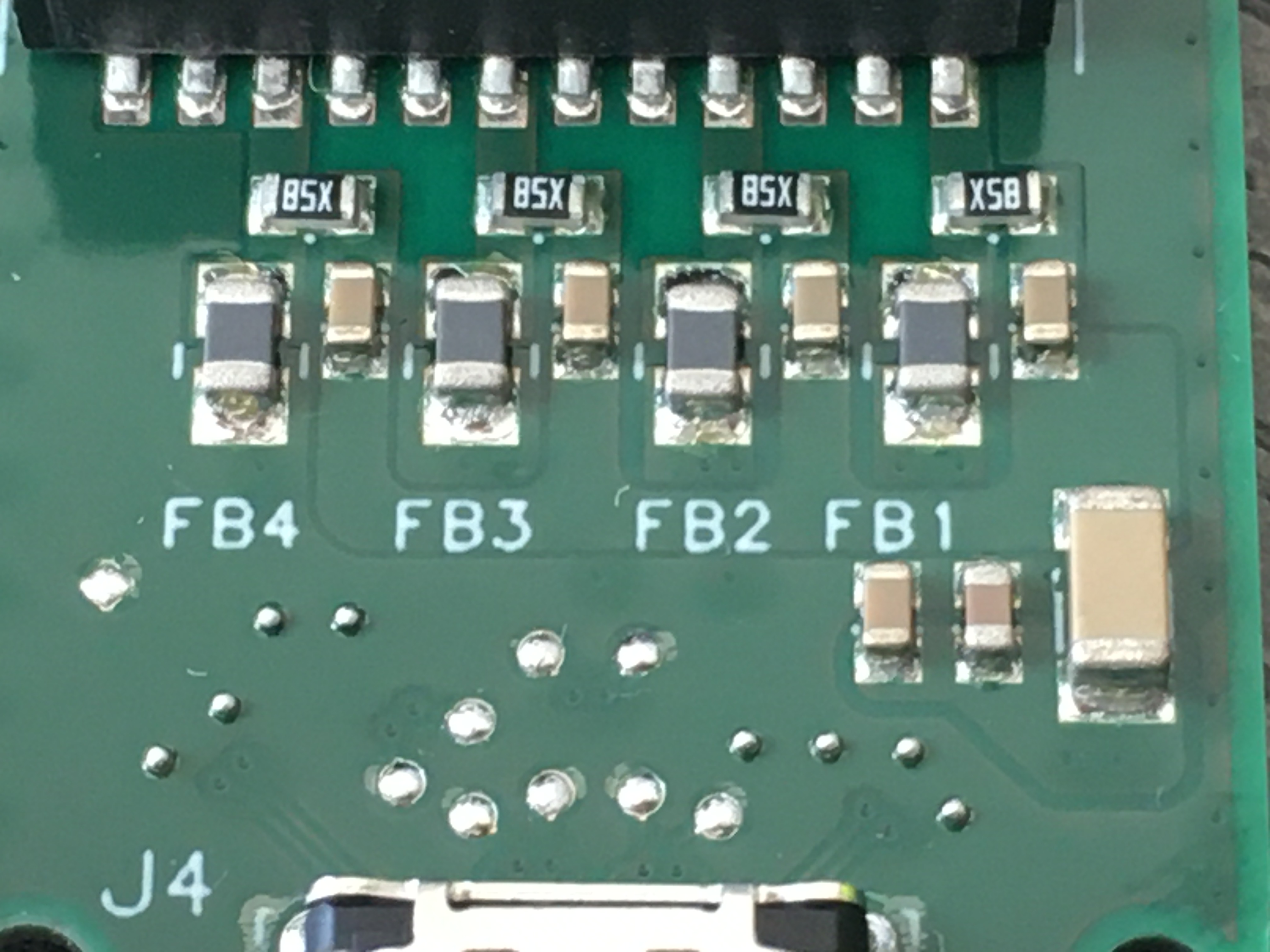
So, the 7490220126 is probably wired exactly the same, but has a different potting material or a higher insulation resistance, or some other spec that is minor enough that it isn't mentioned in the three page datasheets that Würth Elektronik distributes. So, looking at this photo again:
The transformer pins numbers, from left to right, are 13 through 24.
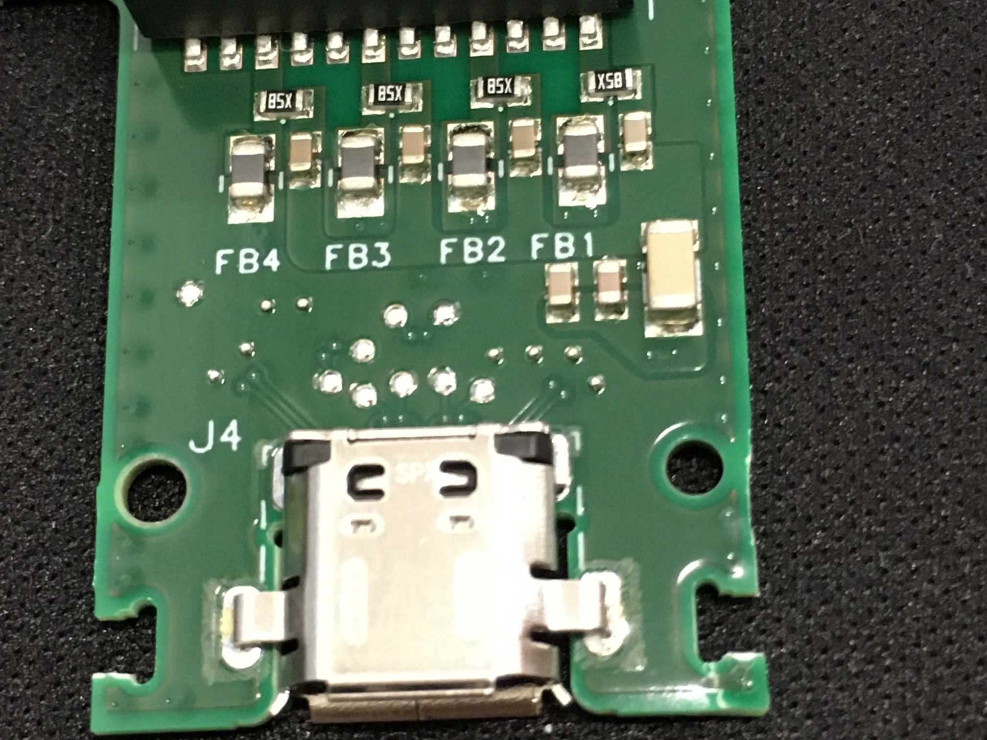
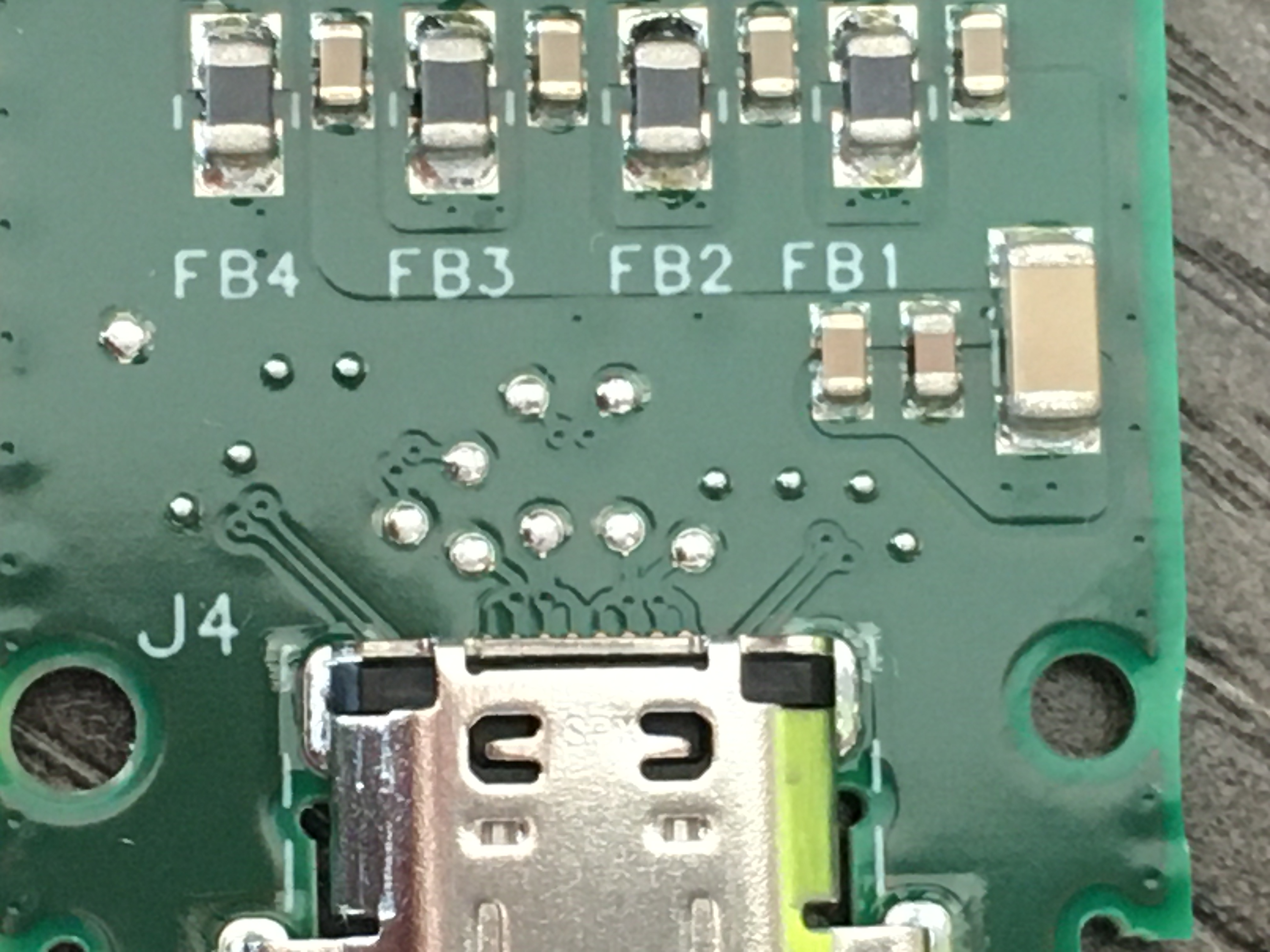
'FB' in this case probably stands for 'ferrite bead', and the other, smaller components are probably related filters. Here is the interesting bit: each of those beads (FBx) is connected to a center tap (CT) on each transformer.
FB4 and FB3 are connected to board ground, FB2 and FB1 are not. This must be the PoE power injection section. So, FB2 and FB1 are connected to the 48 V rail, right? No, actually. Peep this business:
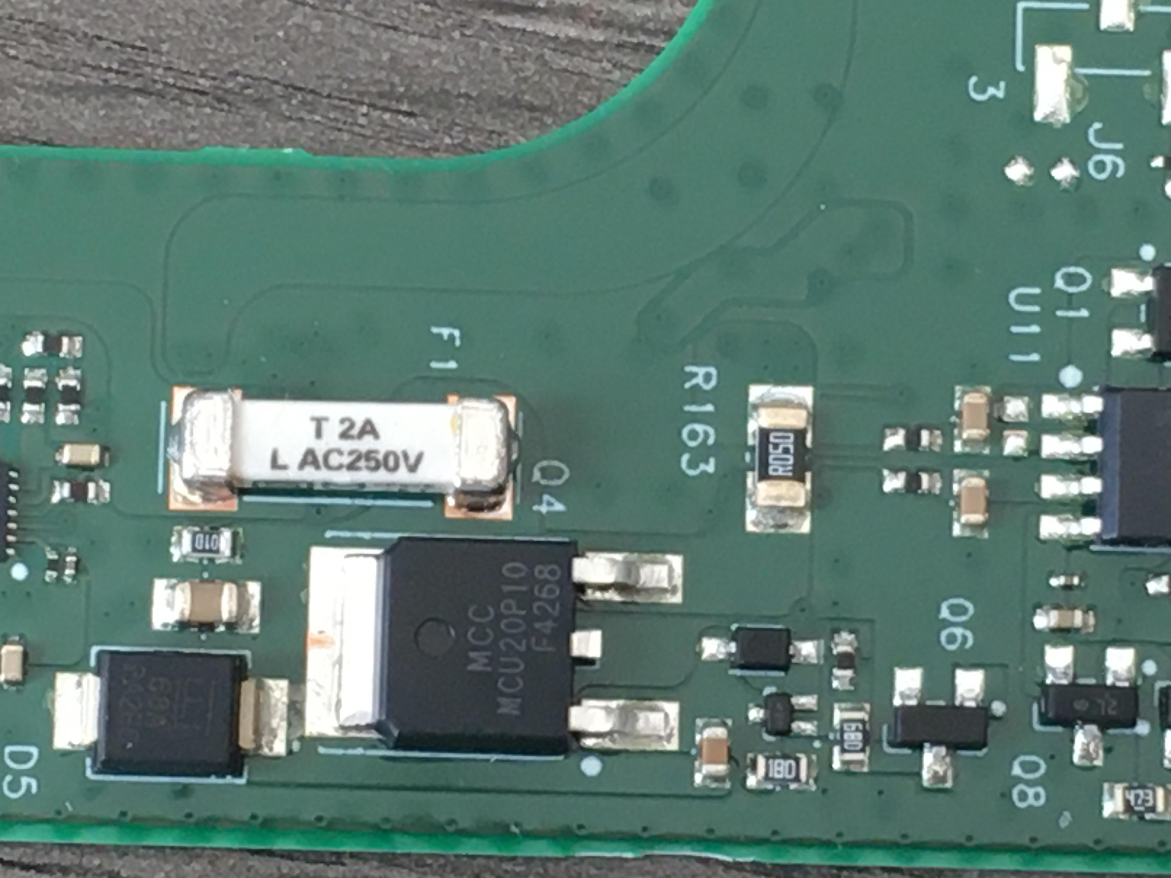
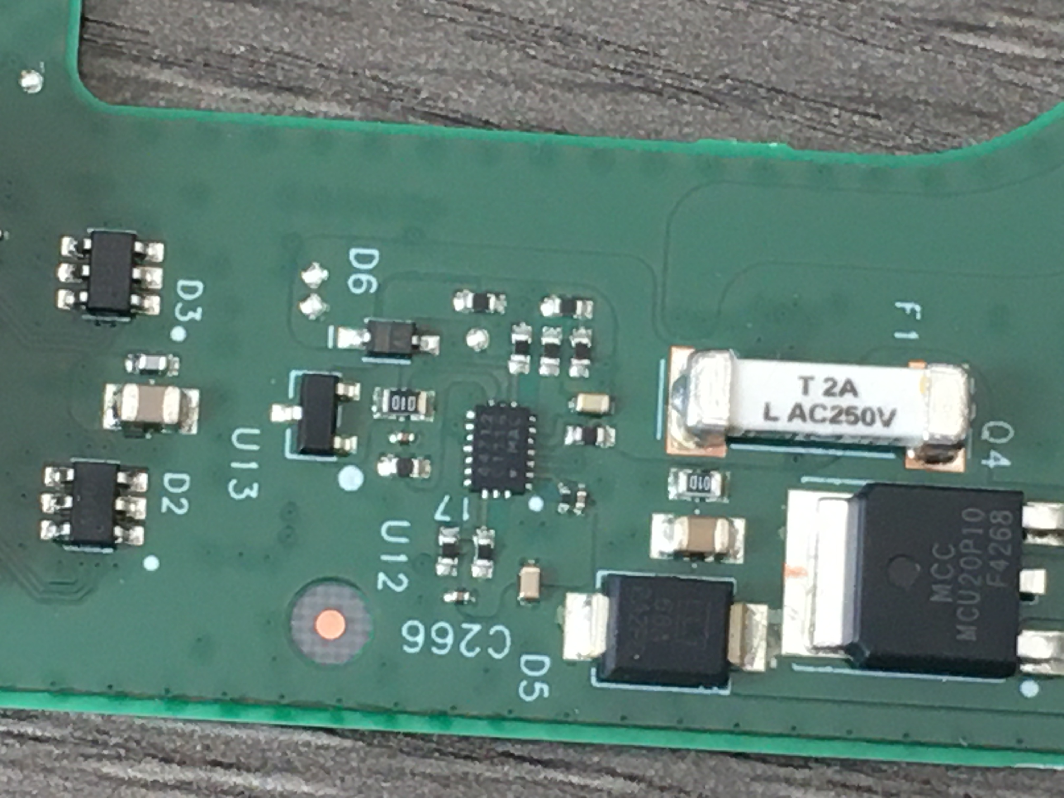 Board traces from FB2 and FB1 appear to go through that fuse and into the tab of that DPAK part, an MCC (Micro Commercial Components) MCU20P10, a rather beefy 100 V, 20 A P-Channel MOSFET.
Pin 3 (top right leg, in this photo) is the Source, and is wired to the 48 V rail from the power supply connector. The tab is the Drain and, of course, connects to the Ethernet transformer. Interestingly, the part is marked EOL - End Of Life, as in no longer produced. Is this a result of the semiconductor shortage? The DPAK footprint is pretty common for power transistors. Did SpaceX engineers make a common footprint, and then source any power transistors they could find, including old stock of discontinued parts? The power control is an unusual feature; it suggests that the Starlink Router isn't just a dumb box - it has some management functionality beyond pushing Wifi signals.
I suppose we already knew this; the official Starlink app doesn't work through any other router - must be some magic in there. So, what voltage is on the cable? What voltage does SpaceX use to power Rectangular Dishy McFlatface? 49 volts!1
1 Unloaded, at least, measured at the power supply connector (i.e. before it passes through power transistor Q4). If you're following along at home, a standard +48 V PoE power supply will work just fine. Just watch those pin-outs. That's probably the next step, map out the connections of Connecty McPropritary Connector.
And finally, more PCB text labels, for the PCB text label search gods:
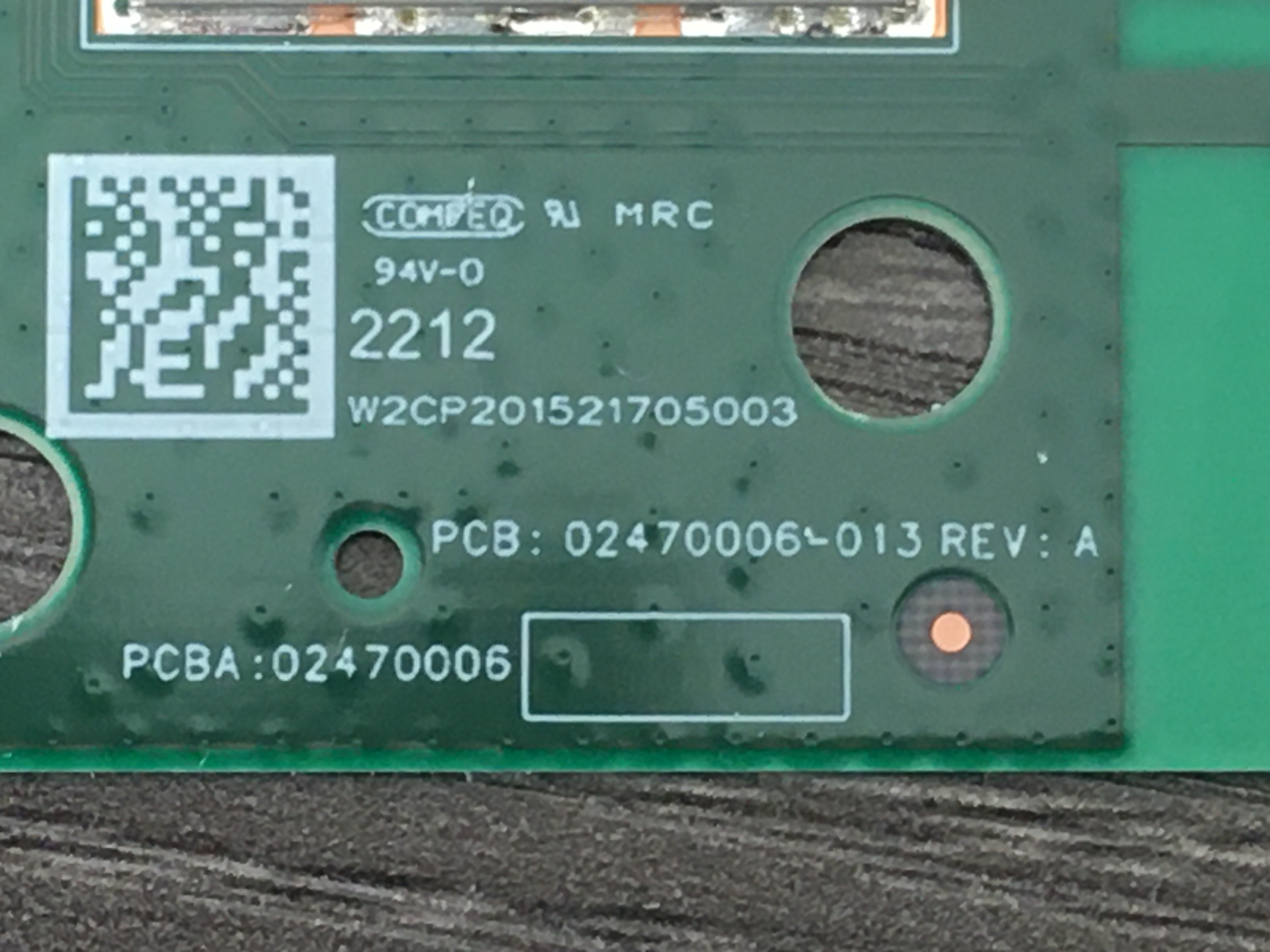
	W2CP201521705003
	PCB : 02470006-013 REV : A
	PCBA : 02470006