

DIY Bench-top Power Supply
Last Update: May 14, 2014
Introduction
Once upon a time I was shopping for lab equipment. On my 'want' list was a proper bench-top adjustable power supply. I had been making do with cheap Radio Shack drek, repurposed device chargers (I use a modified iRobot Scooba cleaning robot charger and Dell laptop power supplies for all sorts of things), 7805s tied in parallel, and various other tricks that would make a proper electrical engineer wince. Unfortunately this professional-grade equipment costs a not insignificant amount of money, as it usually should. I had been given a tour of the inside of a proper professional supply in the not too distant past and had picked up a few pointers: namely that a lot of supplies aren't much more than the common LM317 linear regulator (as opposed to some fancy DC-DC switching circuit), and a large capacitor bank is absolutely critical. So my next thought was "Well, why can't I just build my own?"(Spoiler alert/tl;dr: The homemade power supply will cost about the same as a low end model and won't be as good as a piece of commercial test equipment. Your skills may vary, of course.) Shown here is the route I took and I ended up with something that'll be useful and (hopefully) long lasting. That said, I learned a ton designing and building it so even if it catches fire tomorrow (note to bench supply: please don't catch fire tomorrow or ever) I think it's safe to say I got my moneys worth out of it.
Safety Notice
This project involves main powerline voltage (120 VAC were I live).THIS VOLTAGE CAN KILL YOU.
ALWAYS treat high energy sources (like mains voltage) with respect and observe all safety procedures.
I DO NOT recommend this project to anyone who doesn't have significant experience with electronics and power supplies.
INFORMATION PROVIDED HERE IS SUPPLIED FOR ENTERTAINMENT PURPOSES ONLY; NO WARRANTY OR GUARANTEE IS IMPLIED OR SUPPLIED. USE AT YOUR OWN RISK.
Electronics
For this build I wasn't concerned with if I could expand production to thousands of units quickly so I mostly used parts from local surplus and junk stores, as well as my own junk box.This allowed me to use some rather unique parts and cut costs significantly, at the cost of a little more elbow and footwork. It also resulted in some back-and-forth between the parts store(s) and the design. For example, I'd know I'd need a transformer of some type but I wouldn't define a specification and then go to Digikey with credit card in hand. Instead I'd browse the shelves at my suppliers until I found a transformer that met some very basic requirements (4 amps output at about 25 volts) and modify the design accordingly.
I ended up with the following:
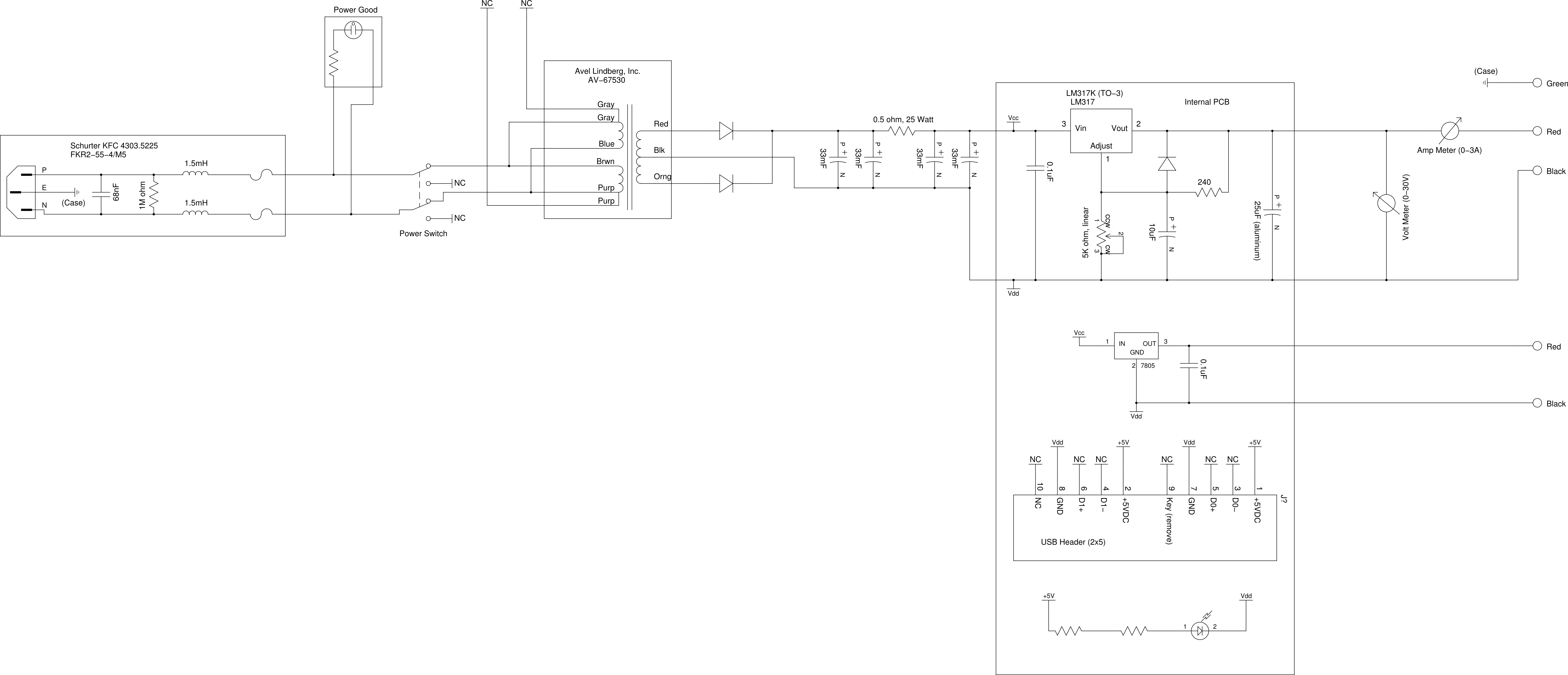 FYI: The schematic above is a general overview; the bill of material differs for the final assembly.
I also developed a carrier board for the LM317K linear regulator, a few extra components, and some handy connectors.
FYI: The schematic above is a general overview; the bill of material differs for the final assembly.
I also developed a carrier board for the LM317K linear regulator, a few extra components, and some handy connectors. 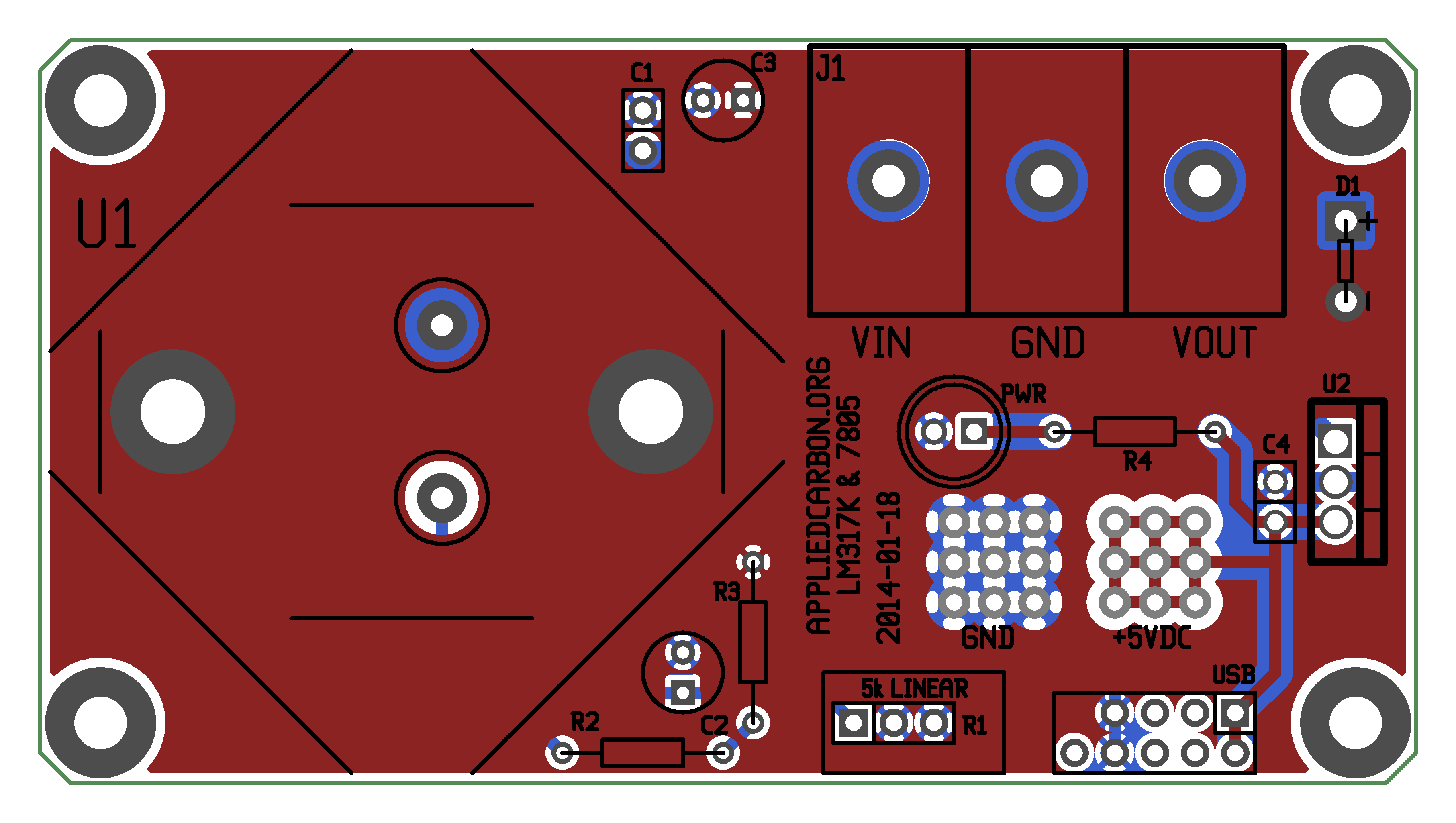
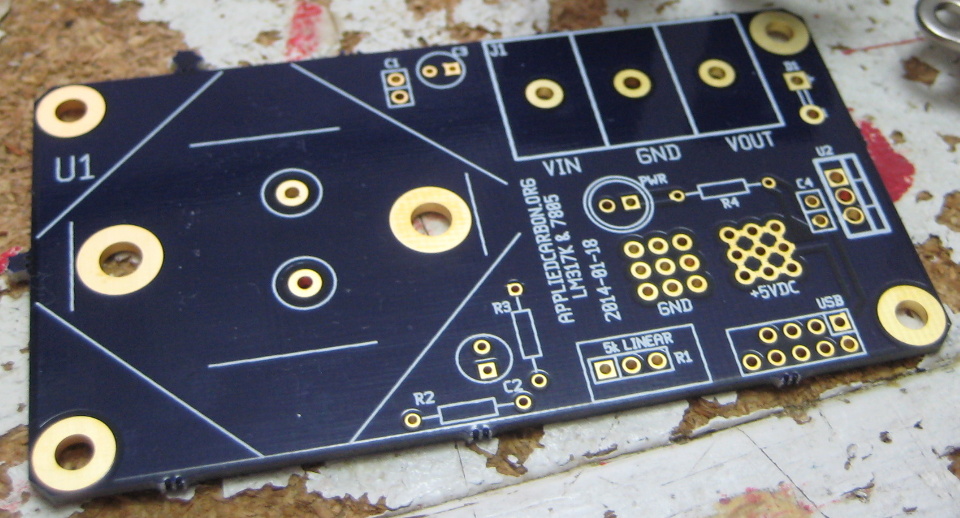 If you want one you can order it here, via OSHPark PCB production service.
I'm also releasing the design files for the whole project under a modified beer-ware license (see included document for details.)
(gEDA PCB layout files / Gerber and drill files / gEDA schematics / high-res images: ac_benchsupply.zip) Okay, so, what parts did I choose and why did I choose them?
I stumbled on the Avel Lindberg Inc. AV-67530 (2x 120V, 2x 25V) at a surplus retailer. A company representative very kindly emailed the datasheet/wiring diagram to me, as well as sending me the mounting hardware that the transformer didn't come with.
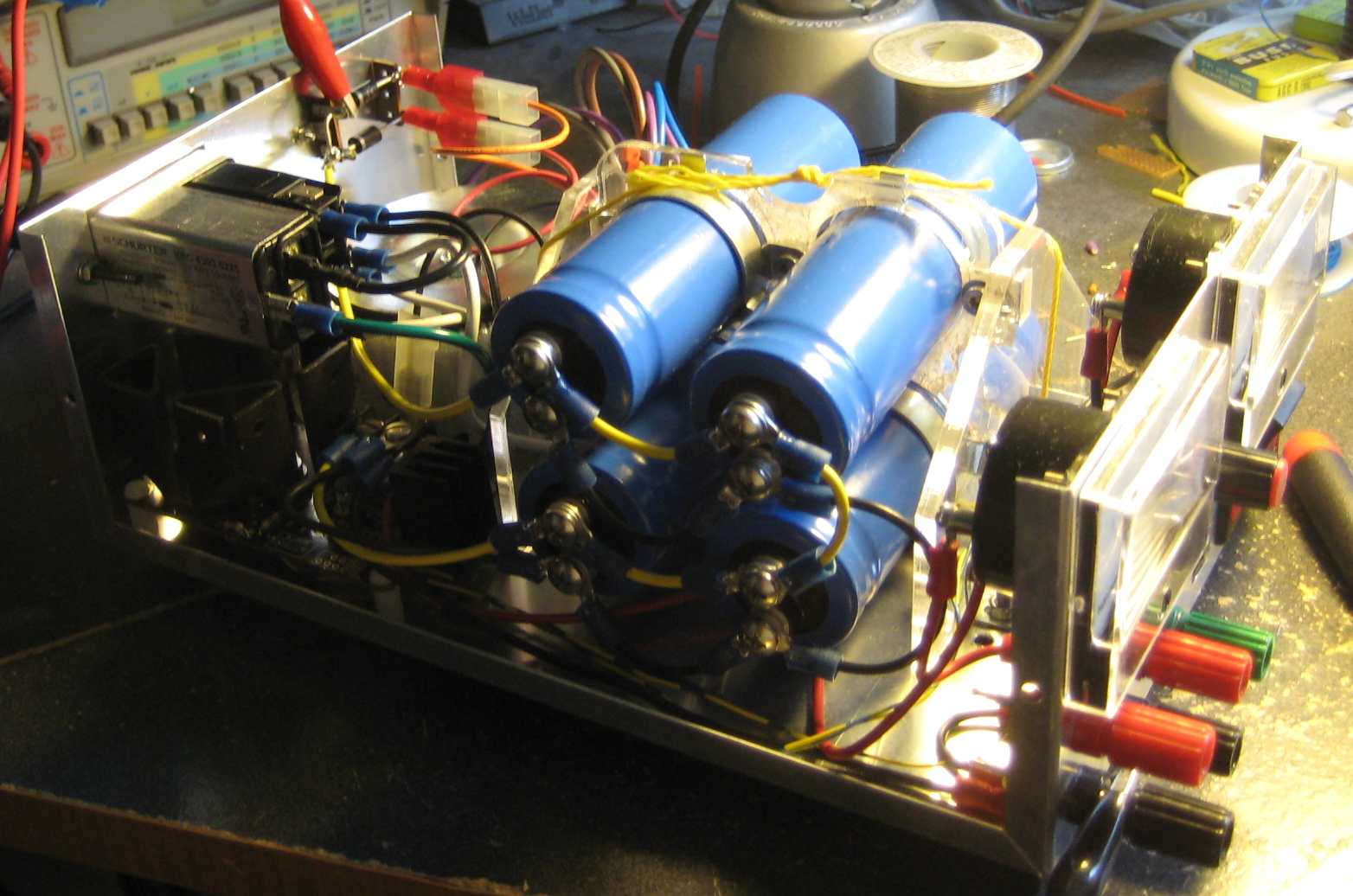
I should note that the design of the transformer is such that the one 25 V output is 180° out of phase with the other output, and not using the center tap would have given me 50 volts at 2 amps which was useless to me (the LM317 implementation in this case has a maximum input of ~40 volts). As mentioned above, a large capacitor is critical for smoothing out line noise and buffering sudden/large drains on current. I picked up four Nippon Chemi-con U32D series computer-grade electrolytic caps. They're rated at 50 volts, 105°C and 33,000 µF. Four of them in parallel give the power supply a total of 132 millifarads, which is enough to keep the internal 'power on' LED lit for a good two minutes. A friend of mine with access to a laser cutter did me a favor and cut out some mounting brackets from a sheet of acrylic, and a trip to eBay netted me a set of 35mm cap clamps. The rectifier was built from a pair of ON Semiconductor MUR405 power diodes and some solder terminal stand-offs I had rattling around in my junk box.
 I used an STMicroelectronics LM317K linear regulator (datasheet). The K-variant is the TO-3 package, a hermetically sealed stainless steel can with superior thermal characteristics. It also looks bad-ass. I made sure to use several large copper plains on the carrier board to help dissipate heat in addition to bolting on a chunky heatsink. After initial testing I'm thinking I didn't put in enough cooling and may add a fan of some kind at a later date; it's almost painful to touch during operation.
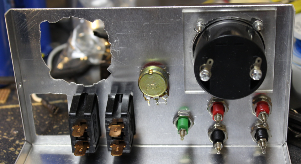
Control is via a 5k ohm linear potentiometer mounted on the front panel. A generic 'Made in China' zero to 30 VDC analog volt meter provides feedback, and a similar generic zero to 3 A ammeter give the user an idea of how much current their project is sinking. I also added a generic 7805 linear regulator. A lot of stuff I work with uses 5V so having that voltage available at all times is useful. At one point I had planned to mount a USB-A socket on the front panel so I could charge cell phones or similar, and hence the header designed for a standard computer USB port expansion plate. I also added a 0.1" grid of ground and +5 VDC holes for powering anything else I might think up in the meantime. The rest of the parts were generic switches and indicators from surplus stores and my own collection of parts.
And crimp terminals. A boat-fucking-load of crimp terminals.
Mechanical
A bench supply isn't much good if it's a pile of wires and parts. I like metal boxes. EMI shielding, strength, superior heat transfer, and grounding to name a few reasons. Too often these days I find equipment built with flimsy, balloon-y cartoon-like plastic cases. Obviously injection-molded ABS is a lot cheaper than sheetmetal, both in terms of mass production and shipping, but since I'm only building one item I'm not worried too much about making more of these.I picked up a generic aluminum sheet metal box and a nibbler tool from a local store, and immediately went to work punching holes in it.
 Yeah, that didn't go so well. Again, my laser cutter friend came through with some acrylic mounting brackets.
Laying out and drilling holes for internal mounts didn't work out so well either. Ate some humble pie (mmm, pie) on that one, but in the end managed to kludge everything together with washers and some fiddling:
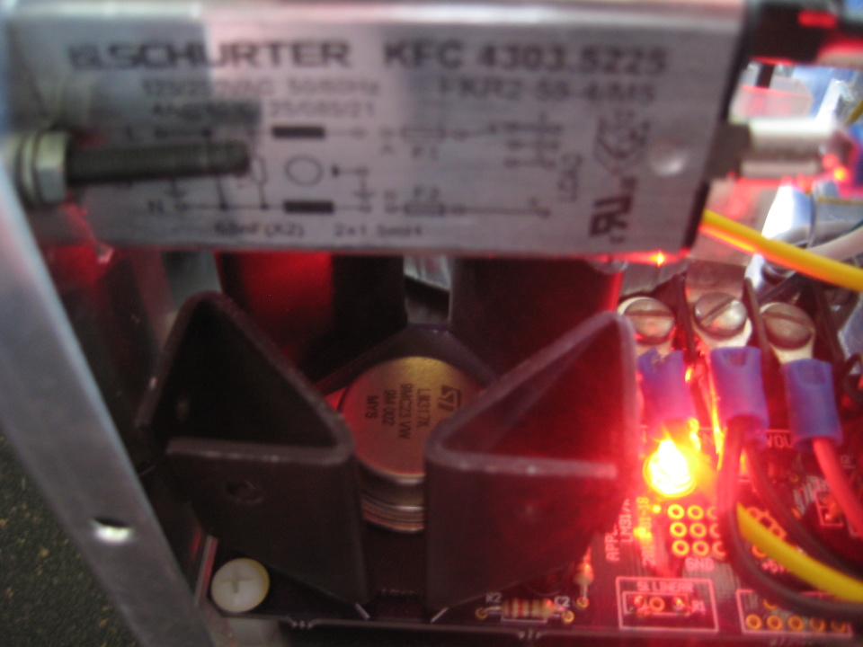
 I tried to keep the wiring color-coded.
White-black is used for neutral-hot 120 VAC, yellow is the ~25 VAC output from the transformer, and red is used for the adjustable VDC output. Green is ground, and connects directly to the metal case. (Make sure your wall socket is correctly wired up, otherwise you may be in for a nasty surprise.) Black is used for the remaining ground lines. You can clearly see the capacitor mounting in the above photo. It's basically a pair of A-frame side panels with a plate between them. I had to have adjacent metal clamps share bolt holes in order to fit the whole assembly inside the box. The yellow cord is pulling the sides in because the angle brackets aren't all that strong and I neglected to add a way to attach the sides to the center panel, beyond some tab-slot features.
Conclusion
Projects aren't without glitches of course.Turns out I cut the height of the capacitor bank really close. One little metal tab on a capacitor clamp is preventing the box lid from going on completely.
The five volt linear regulator outputs anywhere between 3 and 4 volts, depending on the orientation of the stars. It was a part salvaged from a broken CD player so no surprise really.
And finally, the voltage adjustment knob doesn't turn in the same direction as the needle on the volt meter. Not really a failure or anything, but counter-intuitive user interface design. That said, I'm rather pleased with how it all came out. Project = done!