Teardown of a Mitsubishi ST251 Mobile Satellite Terminal
Last Update: August 11, 2018
Introduction
While in the process of looking for UHF SATCOM dishes on eBay, I stumbled across several of these portable satellite phones. The manual for the ST200 series has a copyright date of 2000 - these units were probably designed in the late 1990's and are now obsolete. I picked up this unit for about 100 USD, but I found evidence that a full kit of an identical unit was auctioned off by Goodwill for a whole eight bucks.Given the low cost, some of the internal parts might be interesting to the radio hobbyist.
Overview
The basic system consists of a base unit with a fold up/out patch(?) antenna, and a handset from where the user can place calls. The antenna is not removable, but the Radio Frequency Unit (RFU), and Transceiver Unit (TU), can all be removed as discreet sub-units with just a few screws. The RFU and TU are encased in metal-coated plastic, presumably for shielding purposes. The battery back (NiMH) is held in with a few clips and is intended to be swapped out readily.Photos and Comments
The base has this rather primitive-looking power circuit which appears to manage switch over and battery charging when using the battery with the external power adapter.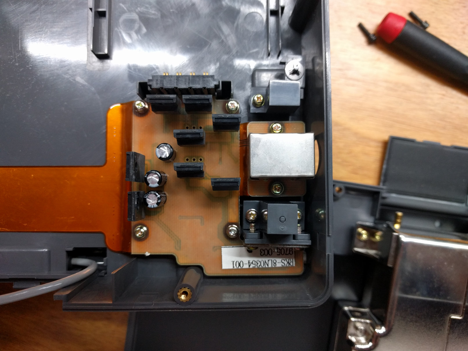
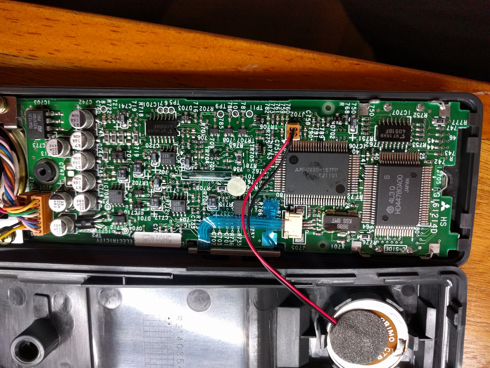
The handset really isn't anything to write home about; it has a keypad, LCD, speaker, and a microphone on the end of a coiled cable. The reed switch in the center is for detecting when the phone is off the hook.
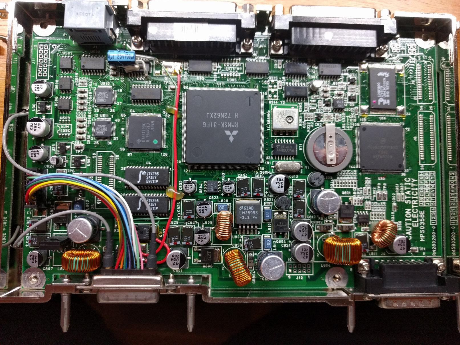
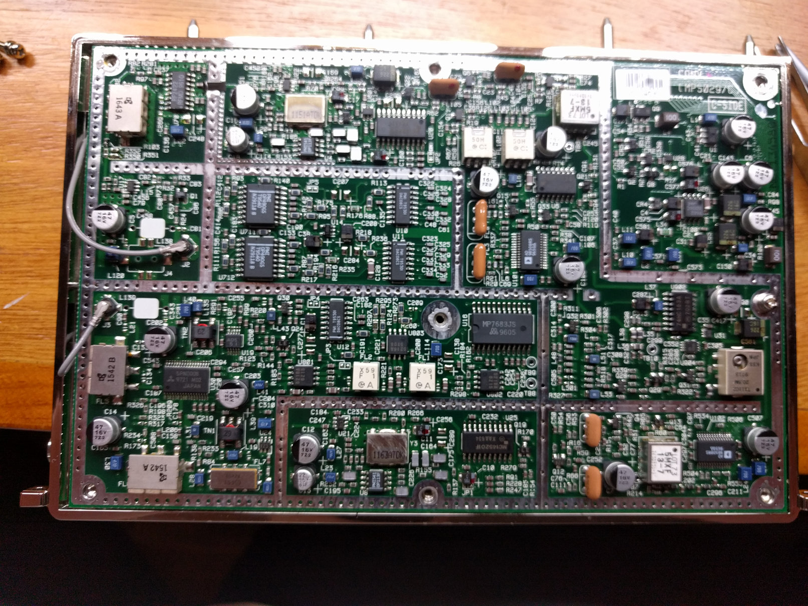
The Transceiver Unit was way more complex than I was expecting.
Check out the rework in the center and how some of the surface mount diodes are angled. Production problems?
The DB-25 connectors at the top are a serial port and a connection for a remote control unit, if memory serves. The connector on the far left is for the handset.
The big ol' chip in the center appears to be custom silicon. If fact a lot of parts in this system are from Mitsubishi. Vertical integration, ahoy!
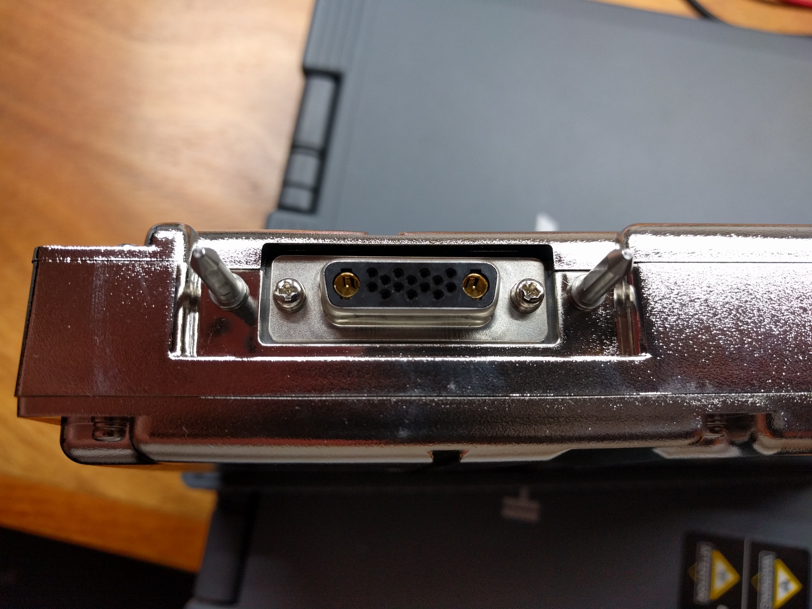
The two D-sub connectors at the bottom (note the wicked alignment spikes) connect to the RFU (left) and power (right). The connector on the right is a typical DA-15, while the connector on the left is much weirder.
Check this out.
Completely custom connector, as far as I can tell. It's unclear why Mitsubishi would make a custom part when various signal+coax de facto standard D-sub connector variants exist.
This particular connector crams 14 signals and two RF connections into the space of a DA shell. I wouldn't be surprised if the two coax connections were I and Q signals (or transmit/receive?), but honestly I have no idea.
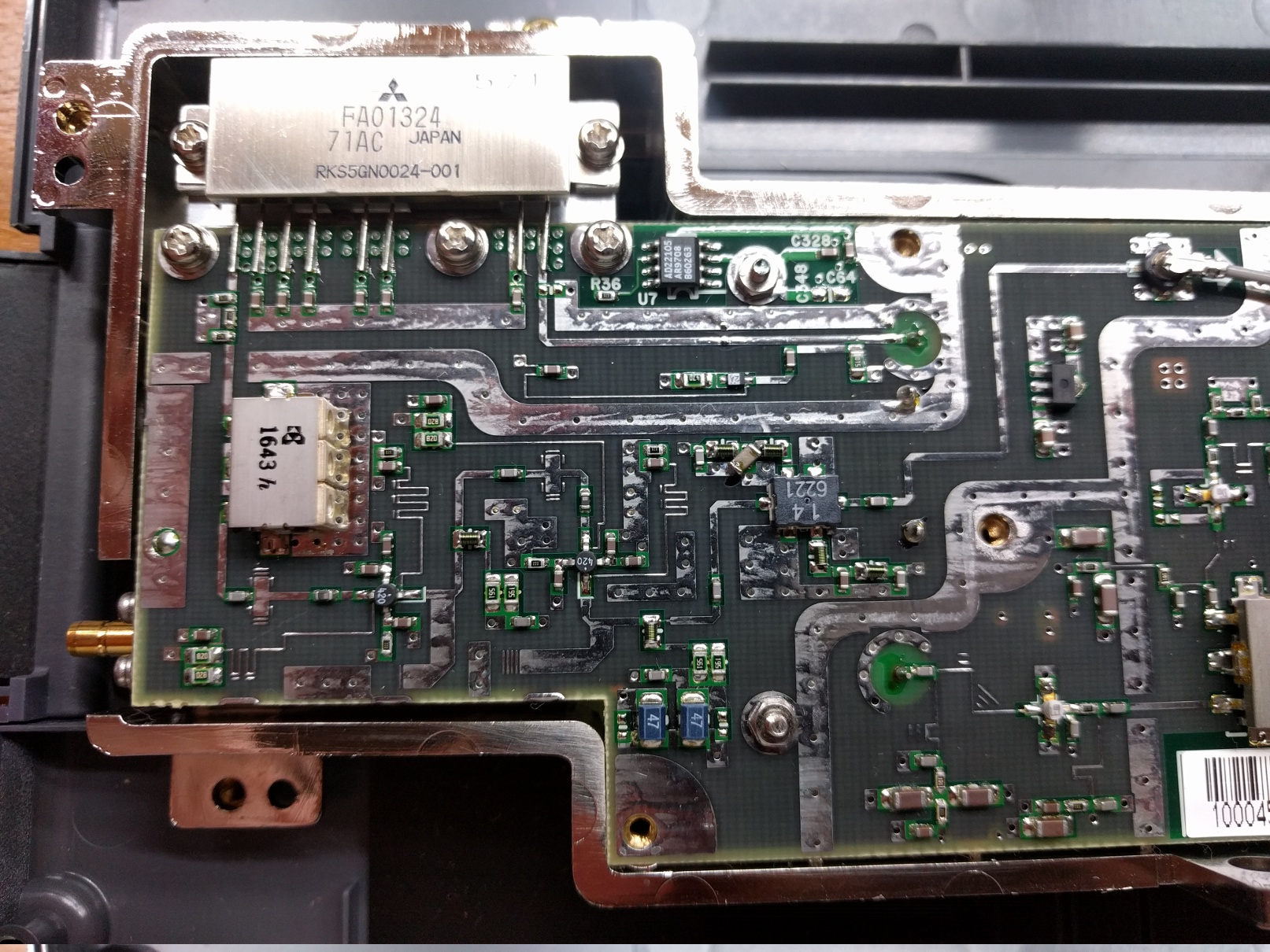
This is the inside of the RFU.
This is only one side of the board, but check out all that microstrip work, and that huge transistor (FA01324 / RKS5GN0024-001) at the top. Antenna connection is at the bottom left.