
Teardown of the Light L16 Camera
Last Update: November 12th, 2024
Main Teardown (March 30th, 2023)
Table of Contents
- Introduction
- Associated Documents
- Opening the case
- Removing the Main Board
- High Res Photos
- Replacing the battery?
- Concluding Thoughts
- Future Work
Introduction
I heard you like cameras, so we put cameras in your camera.
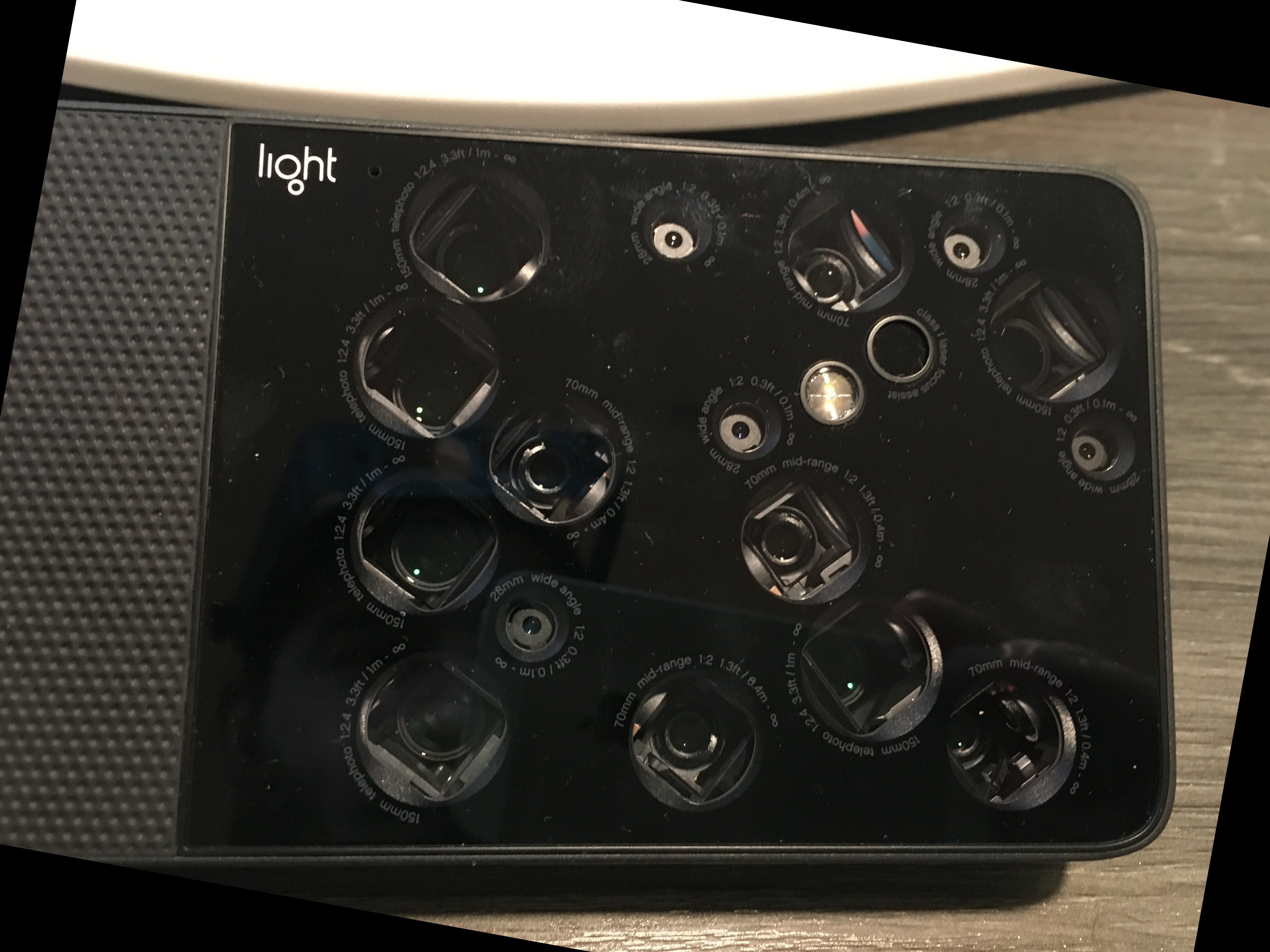
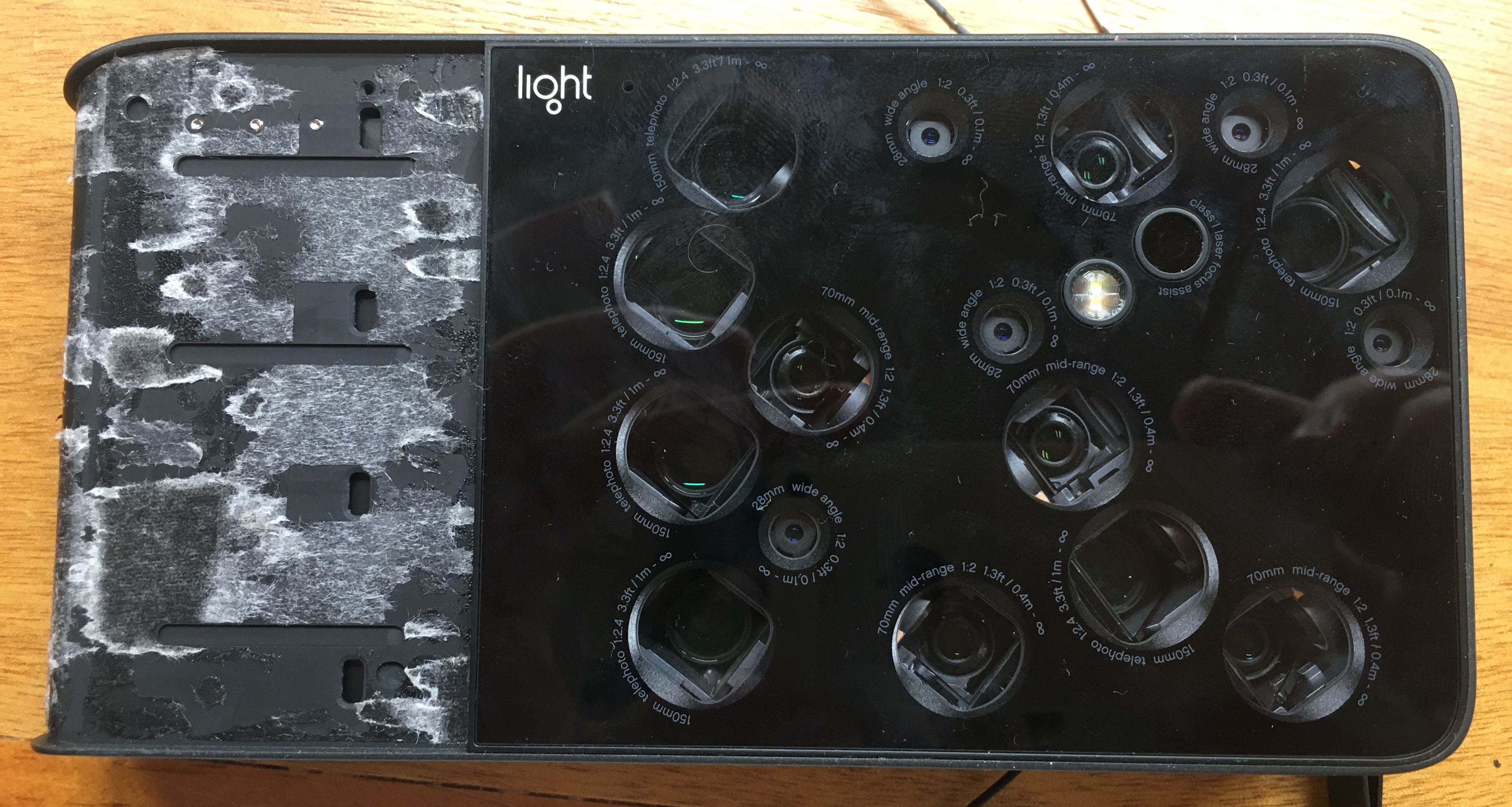
The magic sauce was it captured images from an array of cell phone grade/style camera modules (16 total) of various sensor sizes and focal lengths, and used software to stitch the images together to provide images of about 50 megapixels in size. Additionally, it was to provide telephoto capabilities from 28 mm to 150 mm, all without having a large lens on the front. Cool. Did it work? Nope.
Photos were reportedly filled with glitches and artifacts, where sections would be in high detail (as advertised) but large swaths would be fuzzy messes. During telephoto operation, the view would obviously 'jump' between sensors as the resolution of one was maxed or "minned" out, resulting in periods of poor resolution/visibility.
Additionally, it's size and weight (solid aluminum frame!) put it on the very outside of the 'pocket camera' envelope. Despite these issues, it's MSRP was about $2000.
It reviewed poorly and was generally a flop. The company went under pretty soon after releasing it. Dang. How did you get one? eBay. I found a pair of sale for $50 each. They were listed as 'for parts', with the power light ring thingy blinking red when plugged into USB-C power.
No amount of time on the charger has fixed them. It is unclear if it was a hardware failure or just a dead battery.
Nobody has written a battery replacement guide yet, so here we are. Neato. Carry on. Please forgive some of the non-standard image sizes and aspects. Looks like my image sizing script got kind of confused. Note on photo orientation: All images have been rotated so that the top of the image is the 'top' of the camera - in other words, the long rectangular side with the shutter button. Hopefully this reduces confusion when working on the camera - there are A LOT of connectors and other little parts. For the sake of clarity: in this document, the 'front' of the camera is the side with all the sensors/lenses, and the 'back' is the side with the screen.
Associated Documents
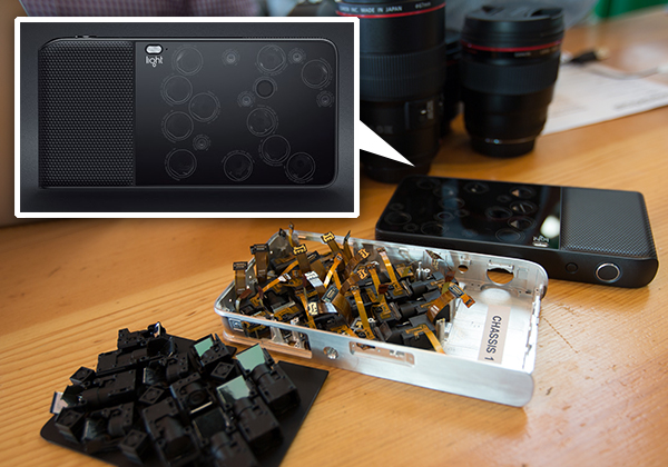
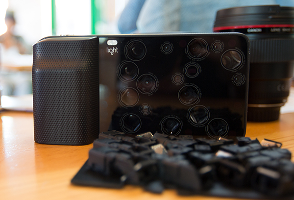
Official development photos.
Following the steps below will damage your camera beyond repair!
If you're looking for a detailed tutorial, this webpage is not it!
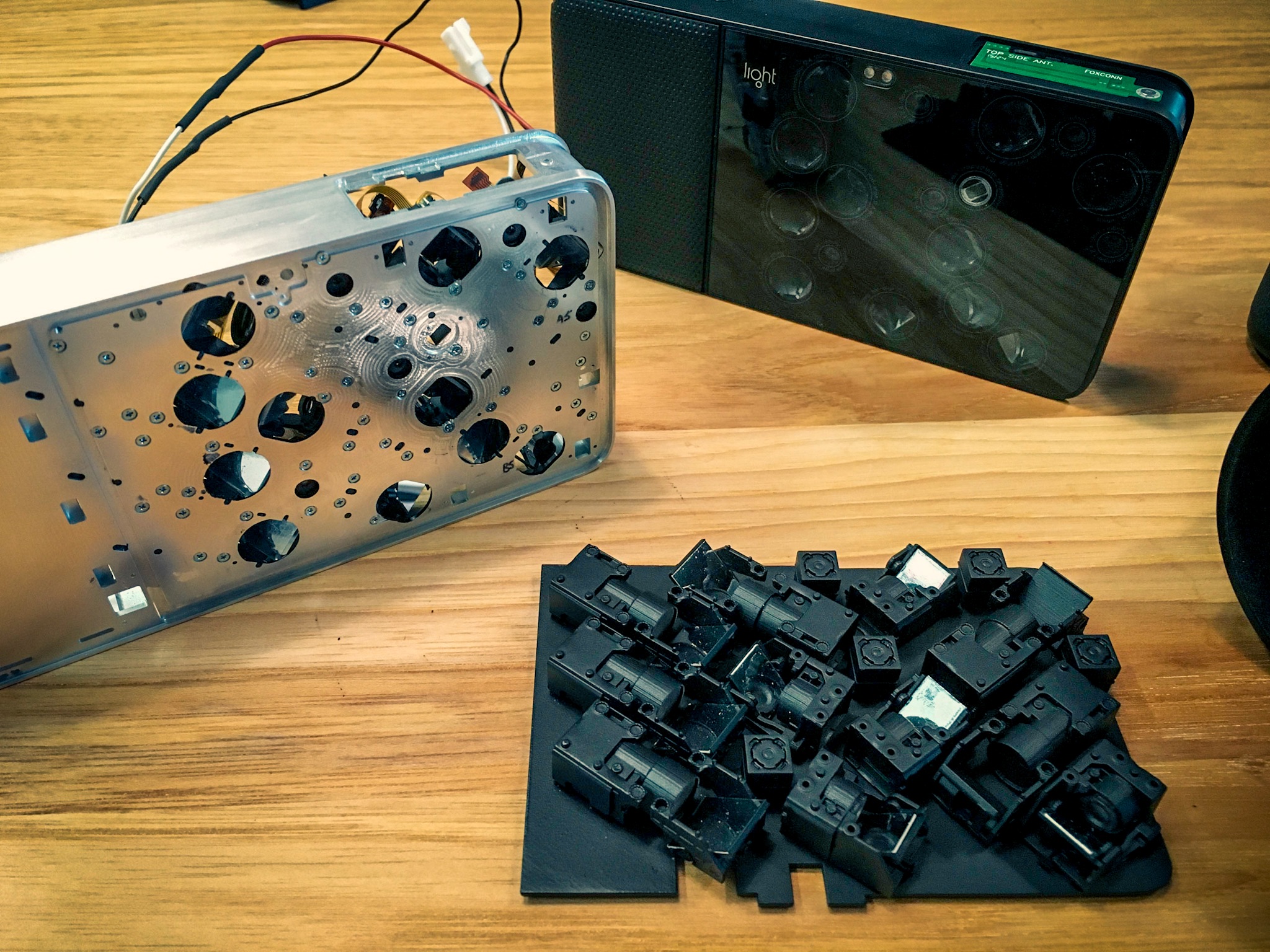
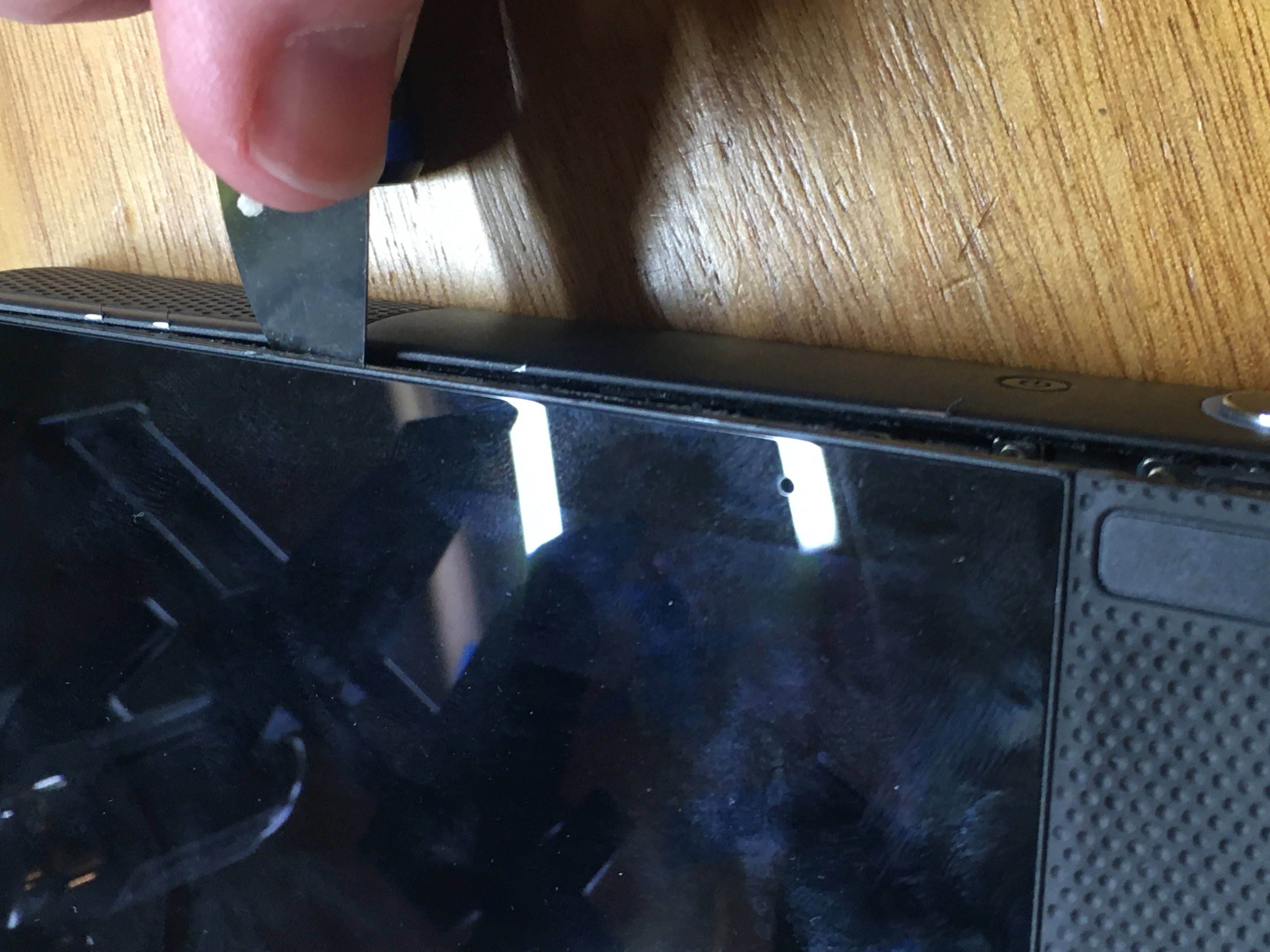
Opening the case
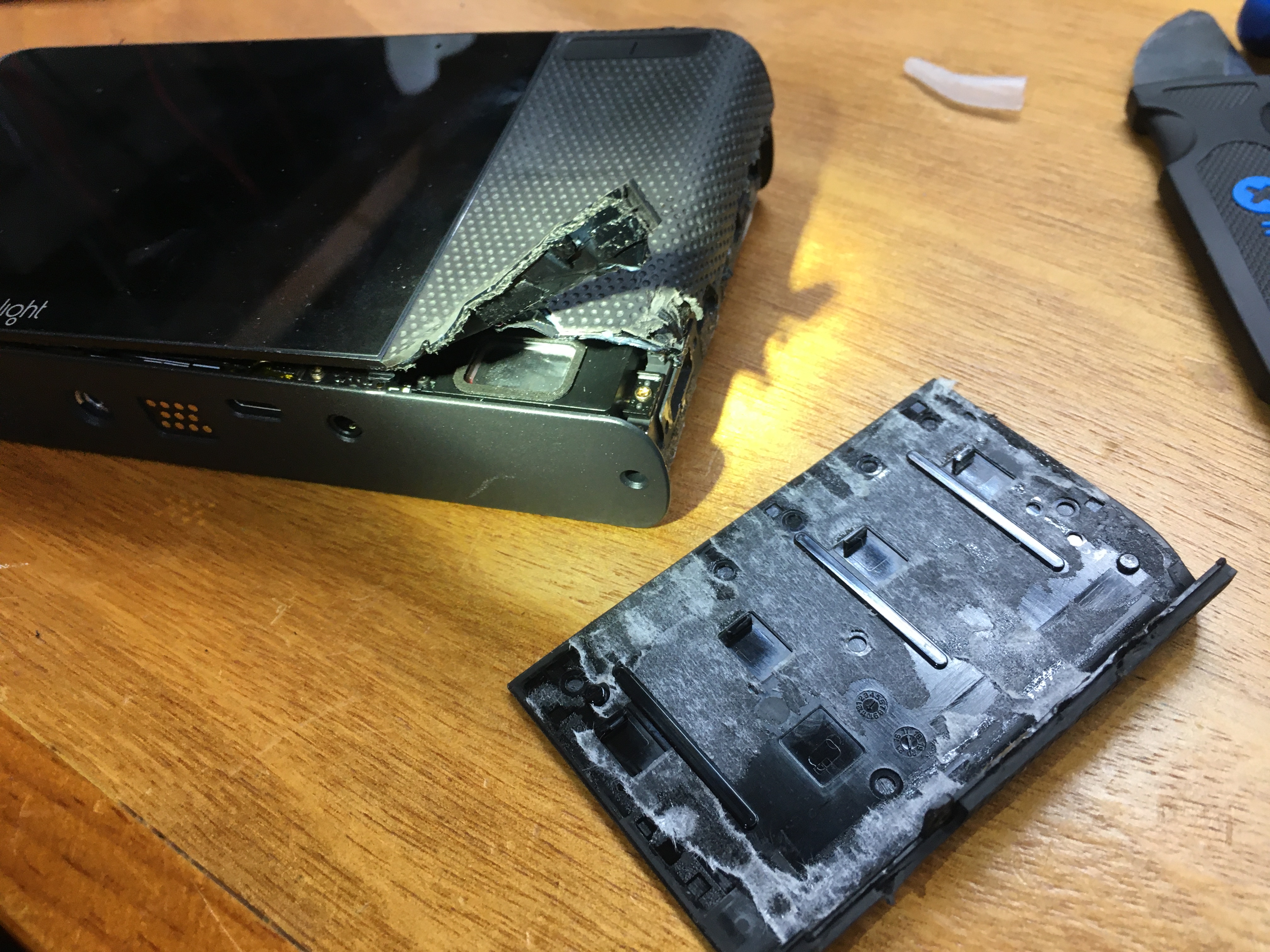
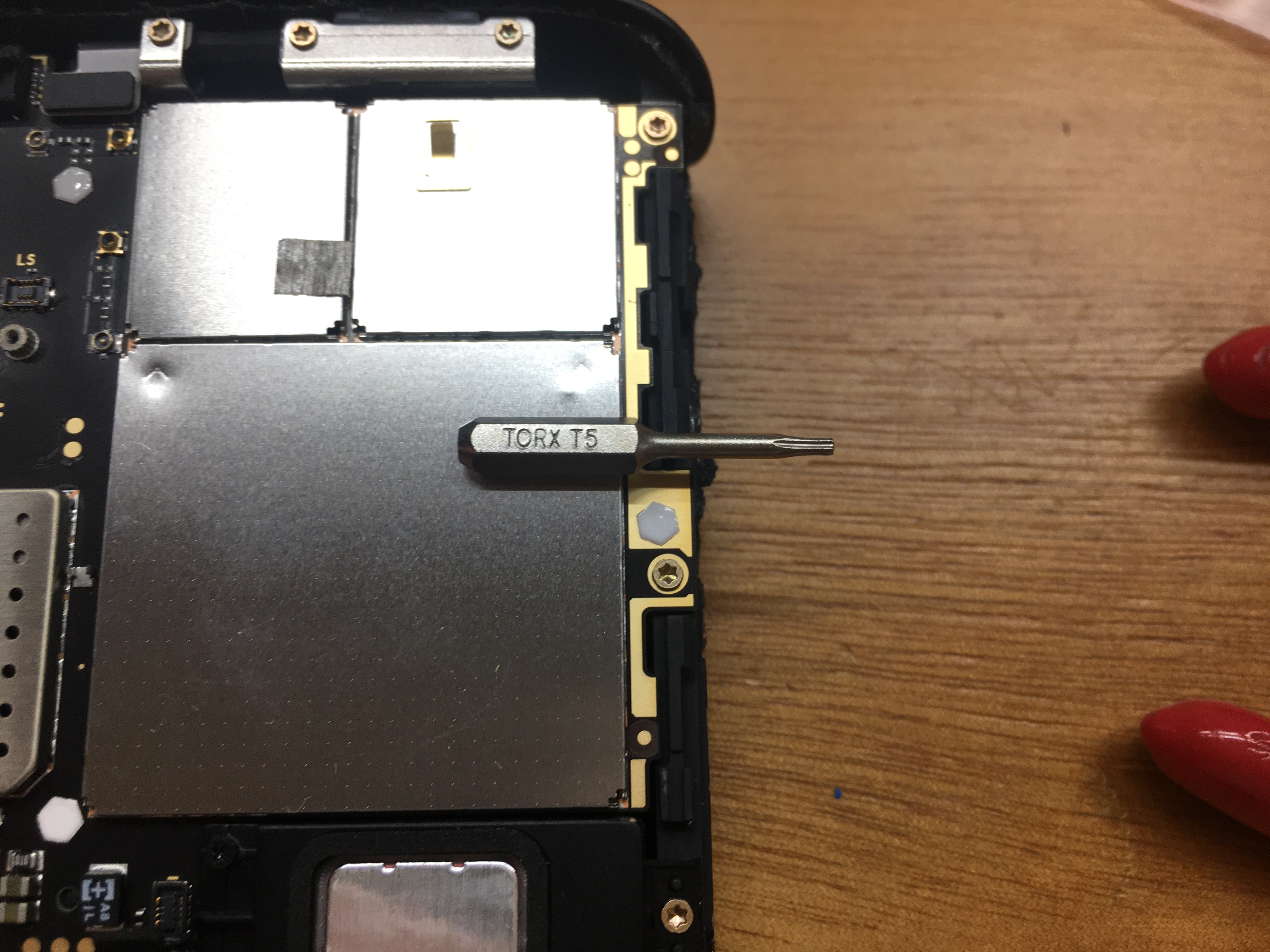
First thing first: the screen assembly pops out of the aluminum frame, and gives access to the internal electronics. Sadly, most of the camera is glued together, so you're going to have to get used to damaging some plastic. The only external screws are on the metal bracket that the wrist strap connects to: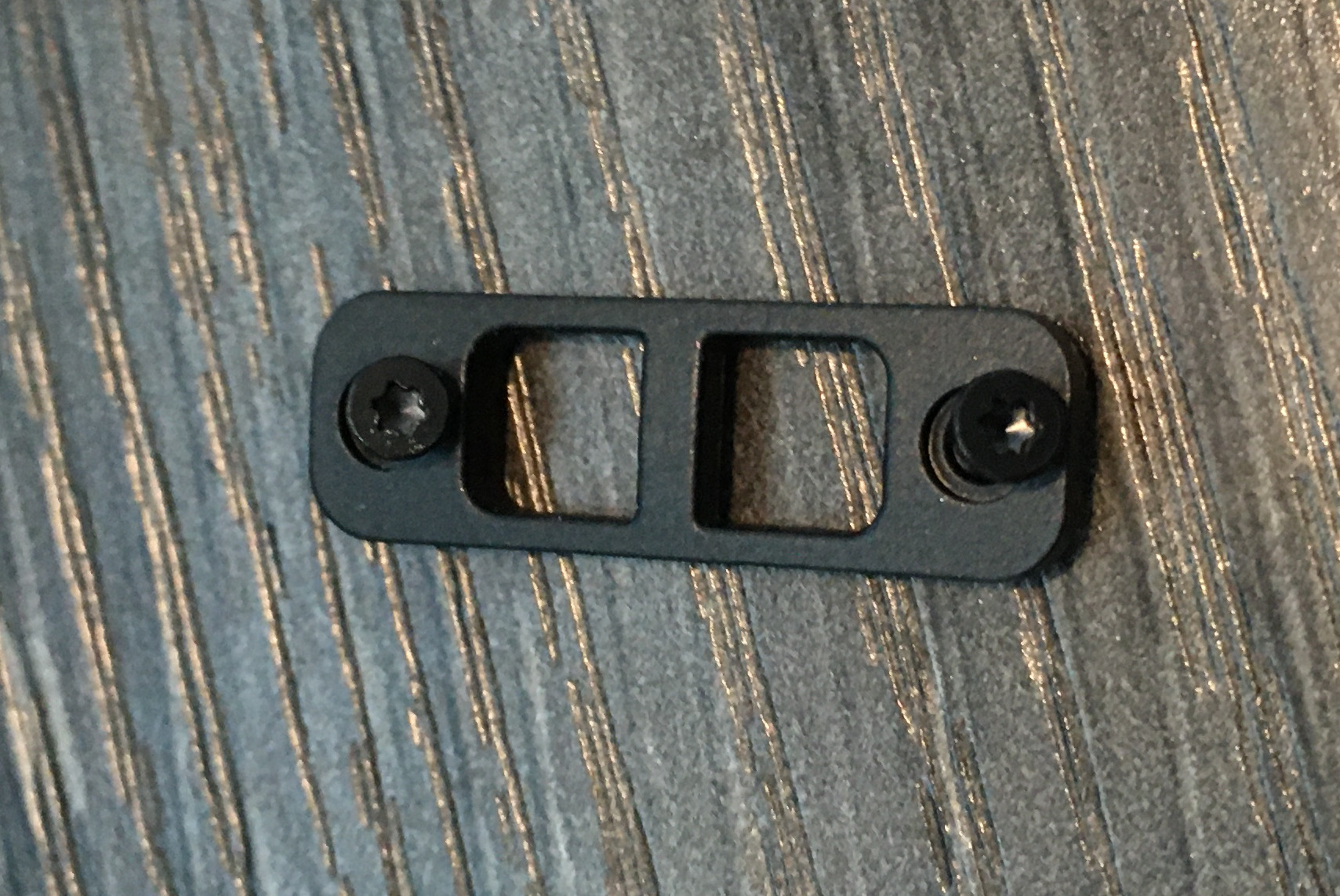
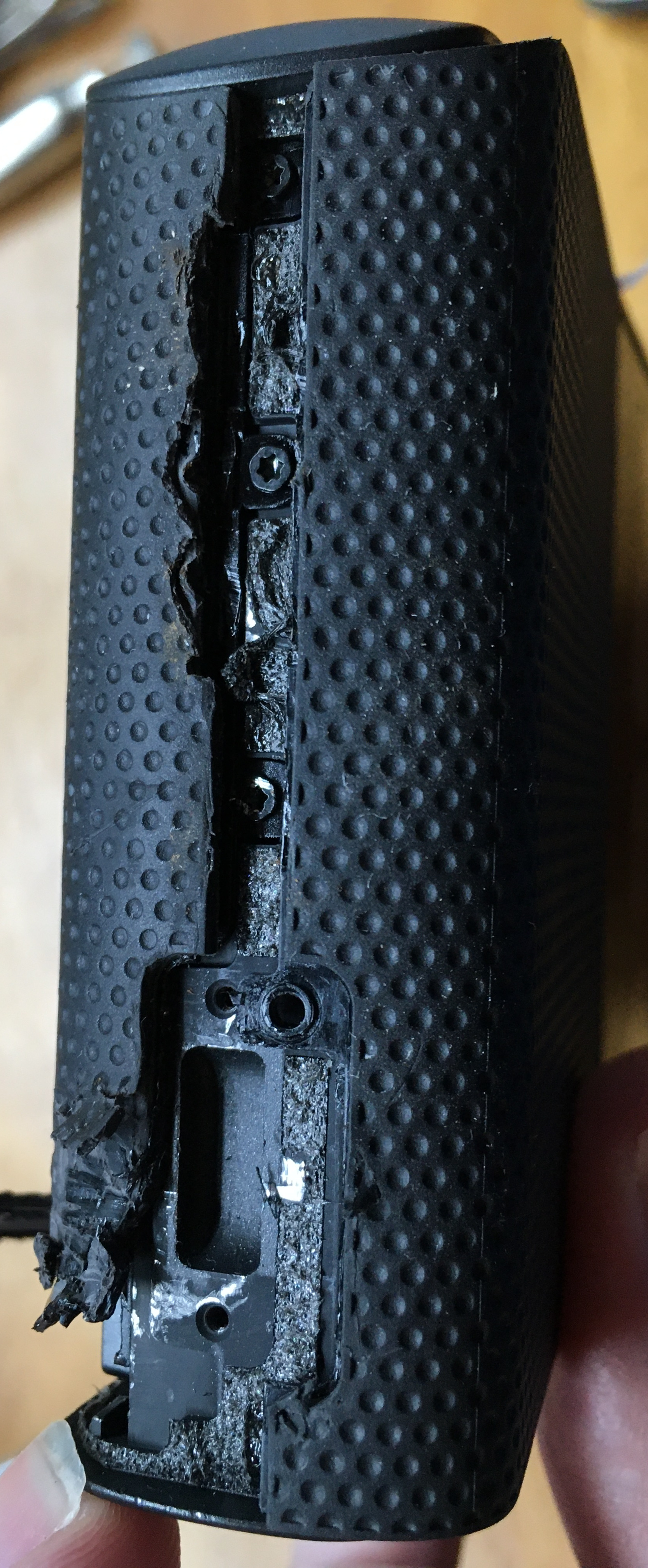
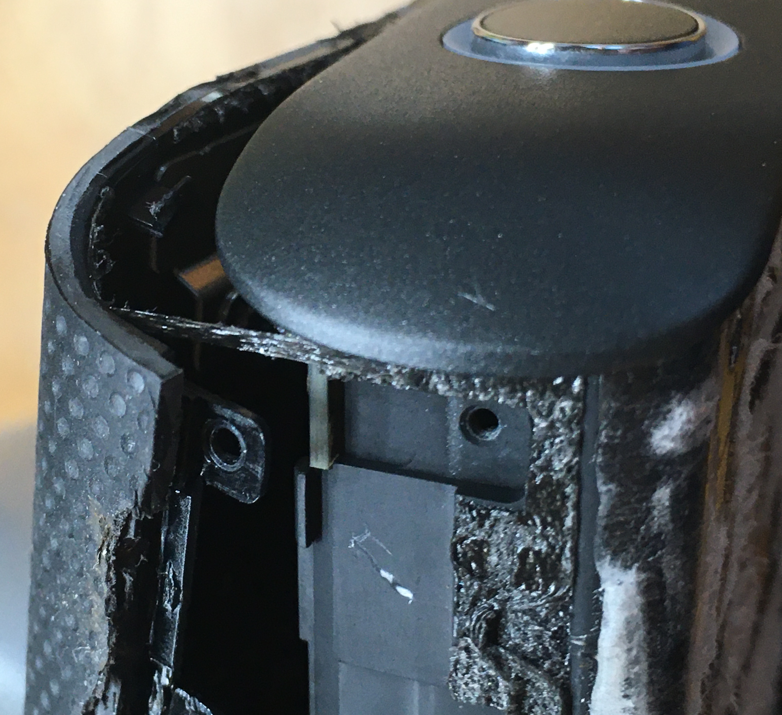
It was non-obvious if the case was fully screwed together or glued, so I did some exploratory destruction:
At this point in my life I should just invest in an X-ray machine.
R-I-I-I-I-P
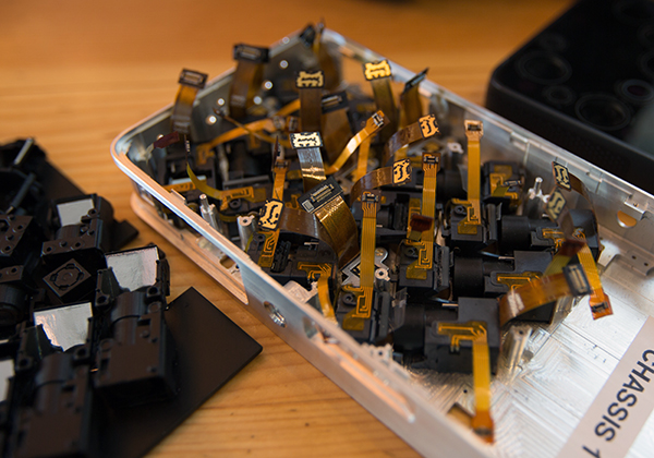
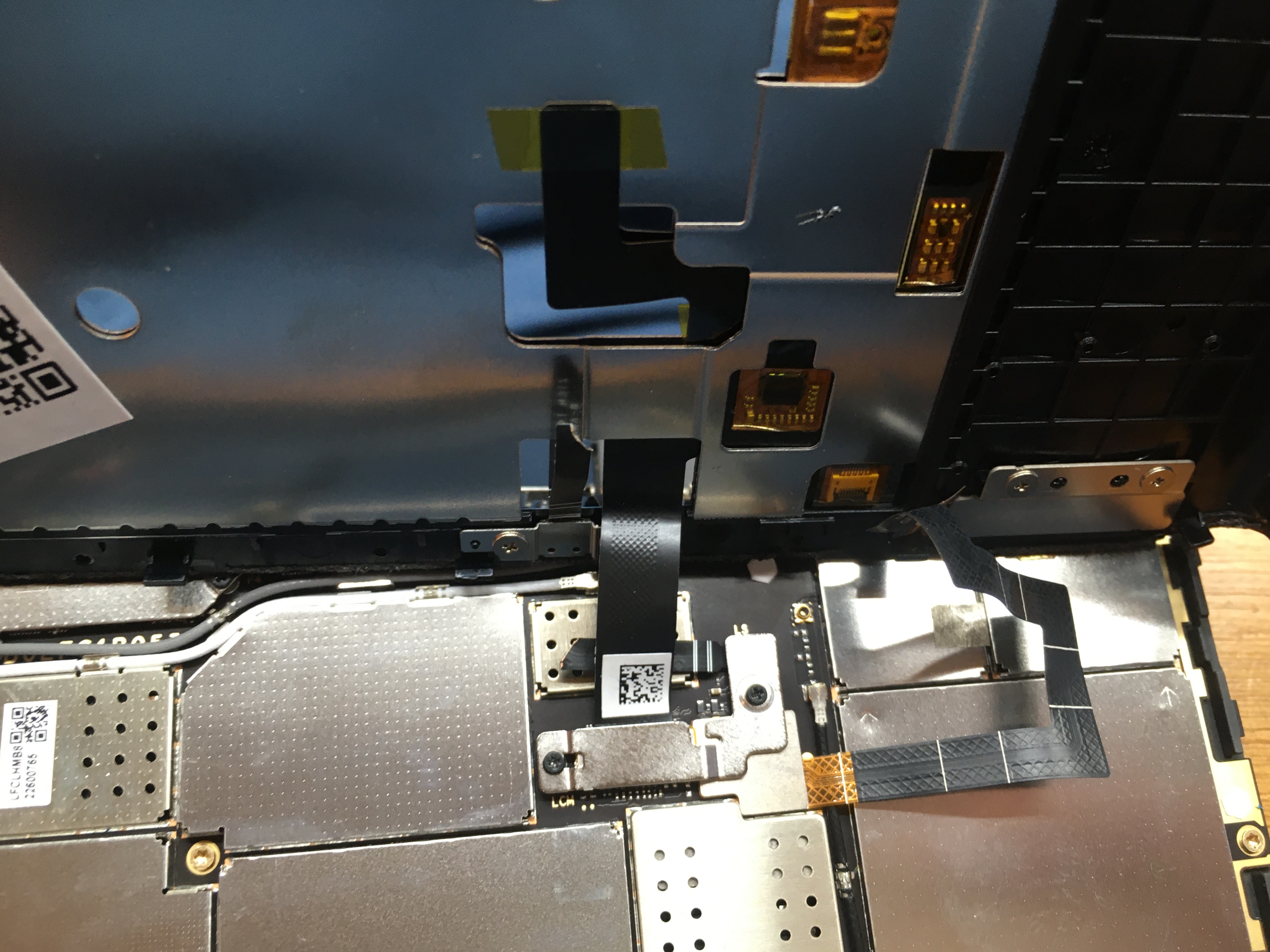
The screen assembly is attached to the main board with several fragile flex cables!
Until these are detached, be very careful when lifting the screen assembly!
I assume they wanted that Apple-esque 'clean' look, but having to drill through plastic just to open the camera is astoundingly poor design.
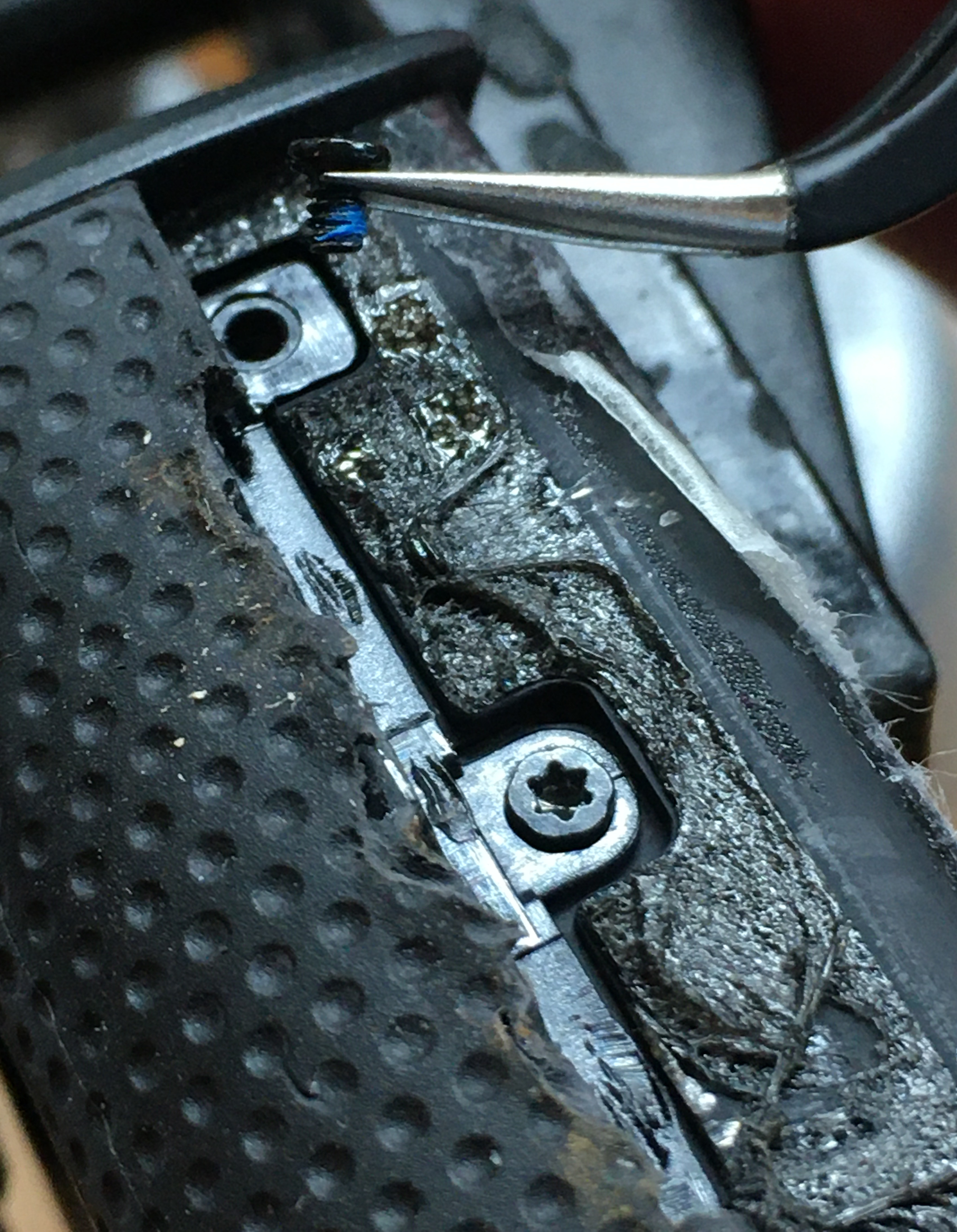
Screw locations on the right side
Peel off the left side bumper...
Screw locations on the left side
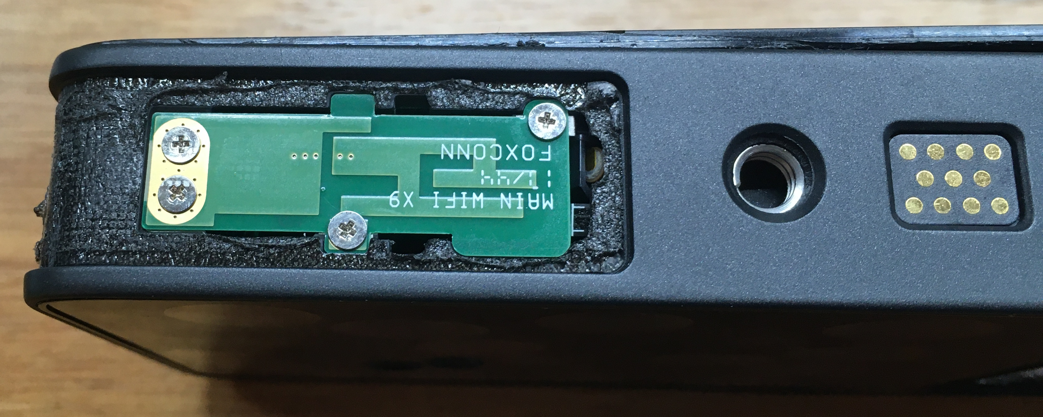
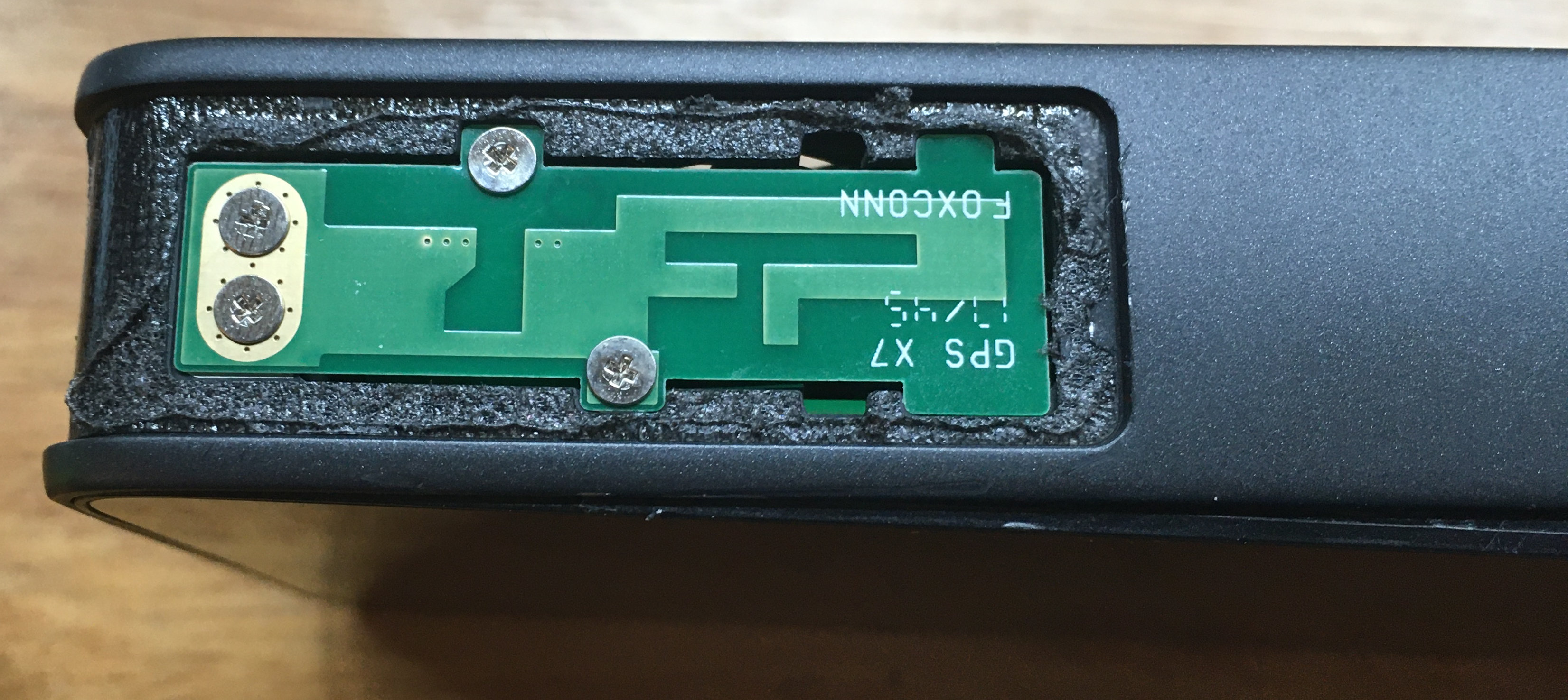
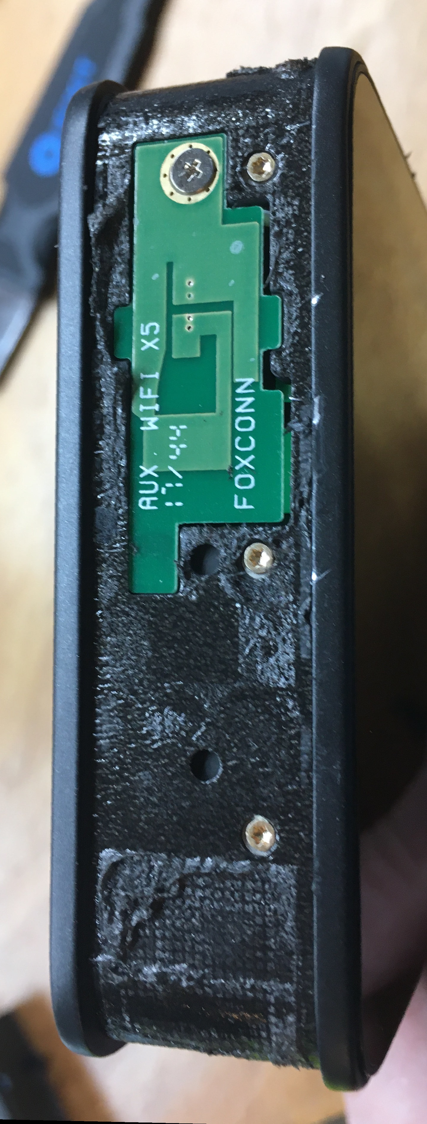
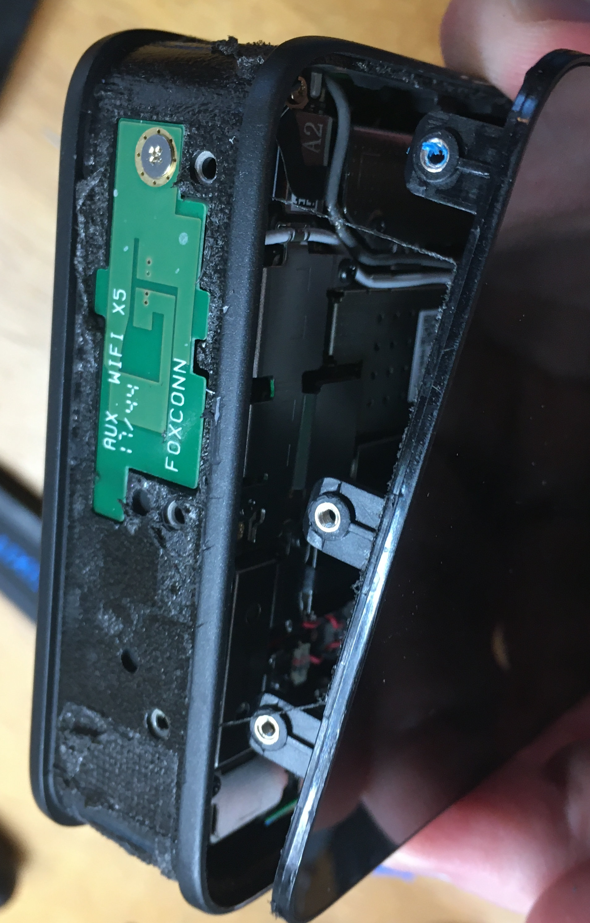
Bonus shots of the Main Wifi and GPS antennas
Note the glue around sections of the perimeter
The screen assembly is attached to the main board with several fragile flex cables!
Until these are detached, be very careful when lifting the screen assembly!
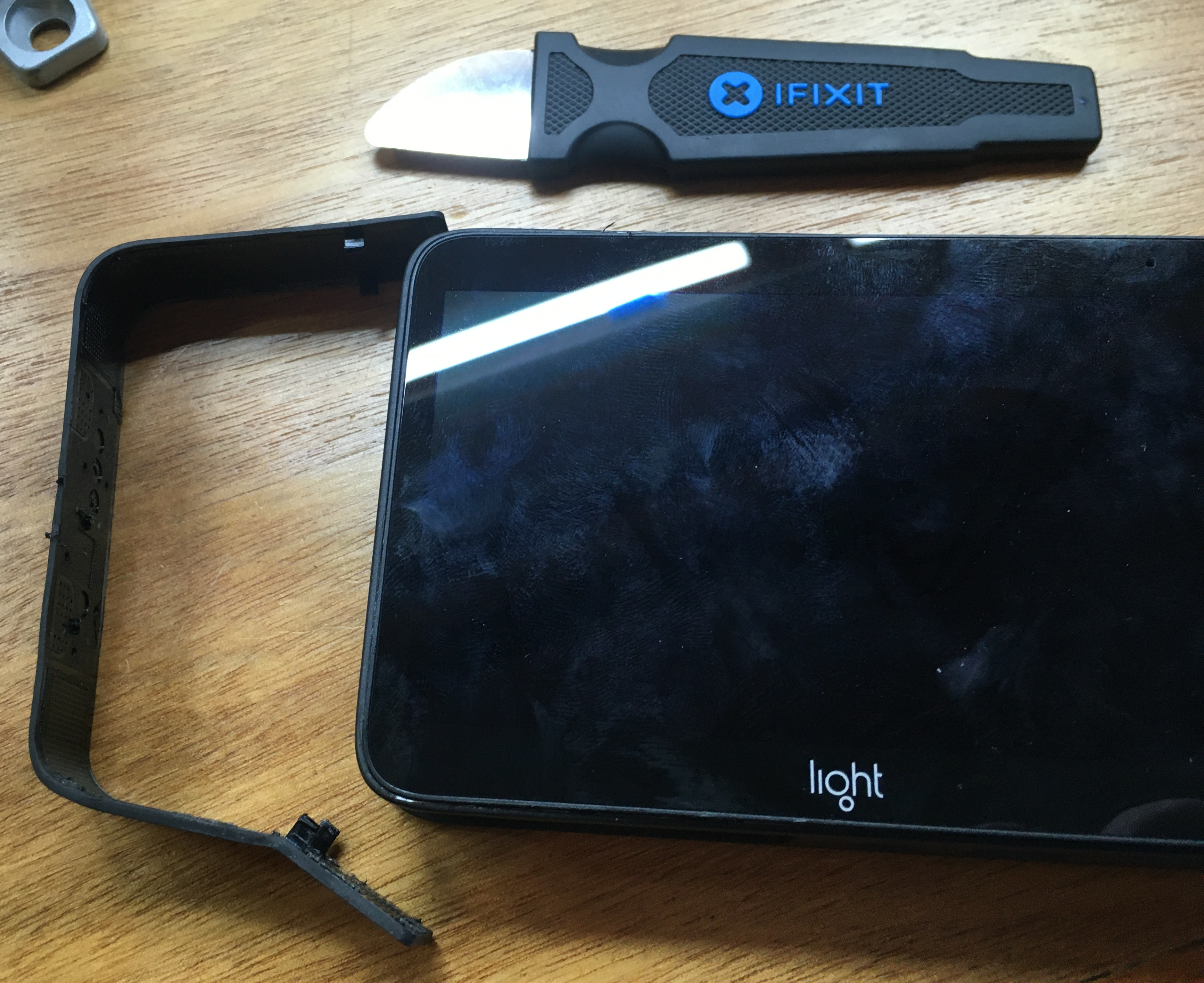
At this point, the screen assembly should be free, and one may tip it 'up' - lifting from the edge along the bottom.
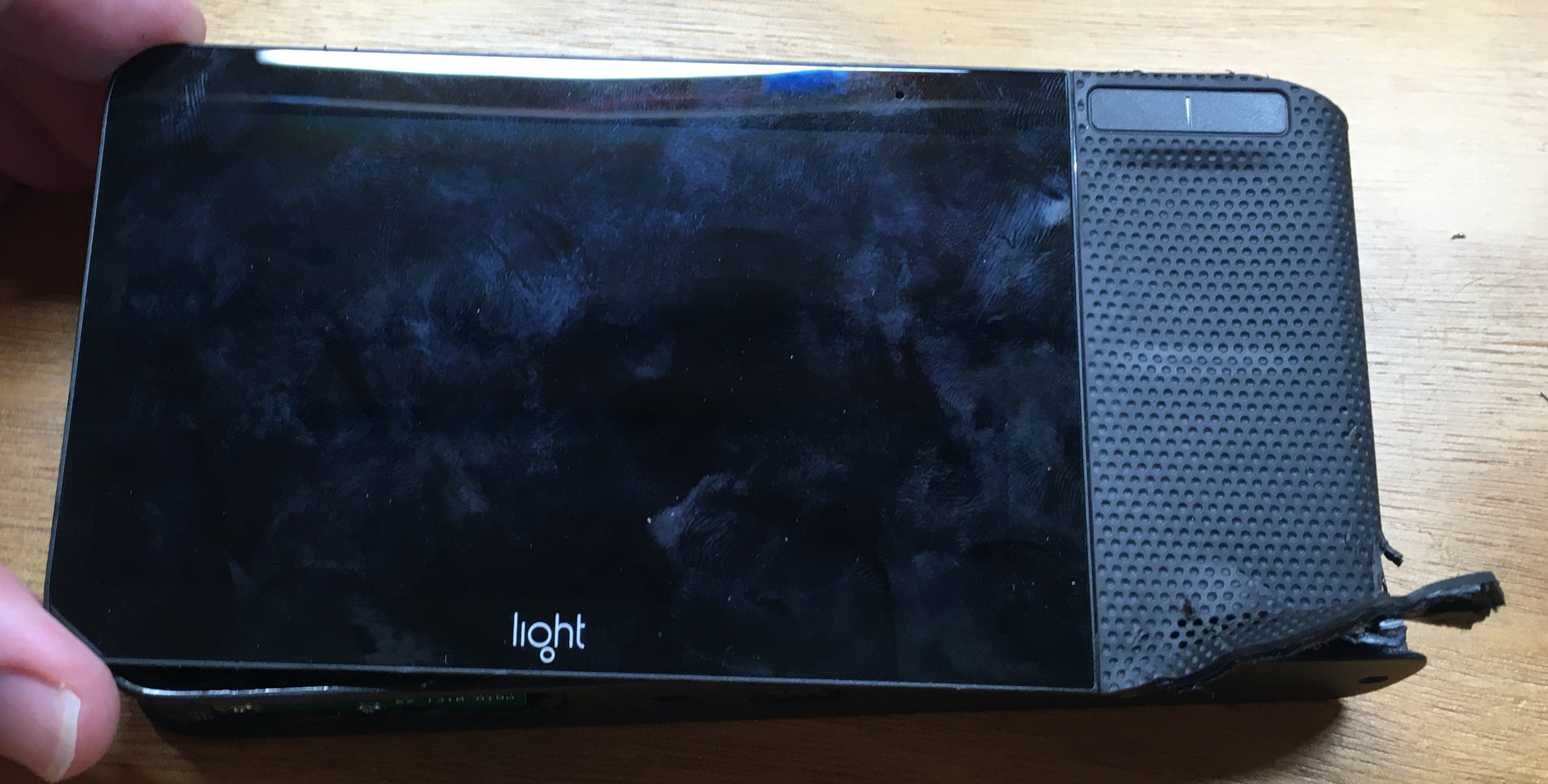
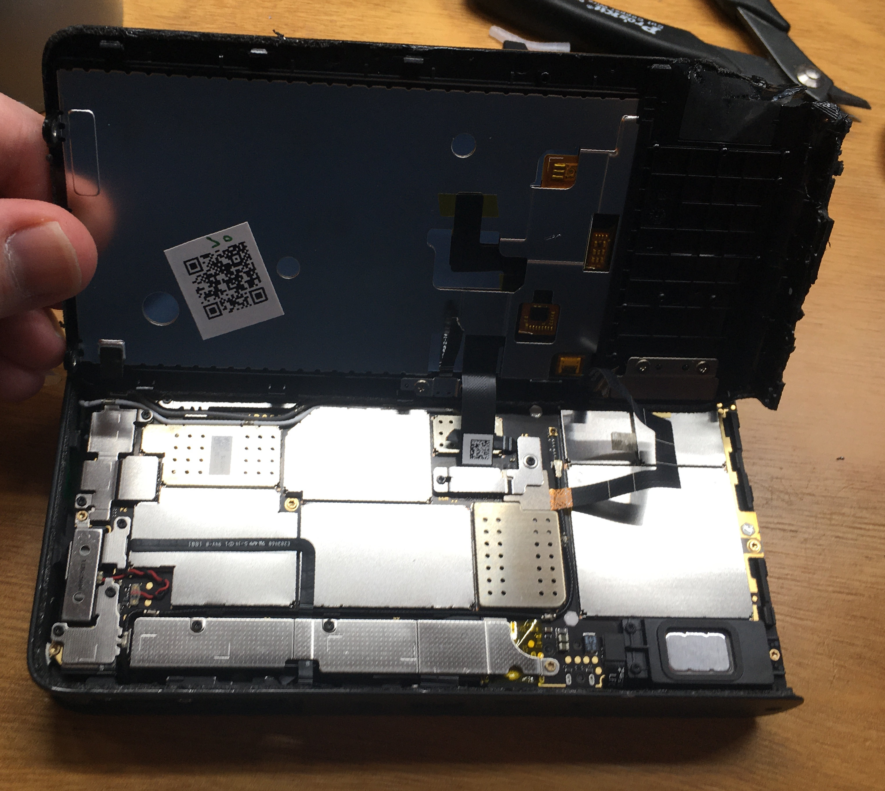
Ta-da!
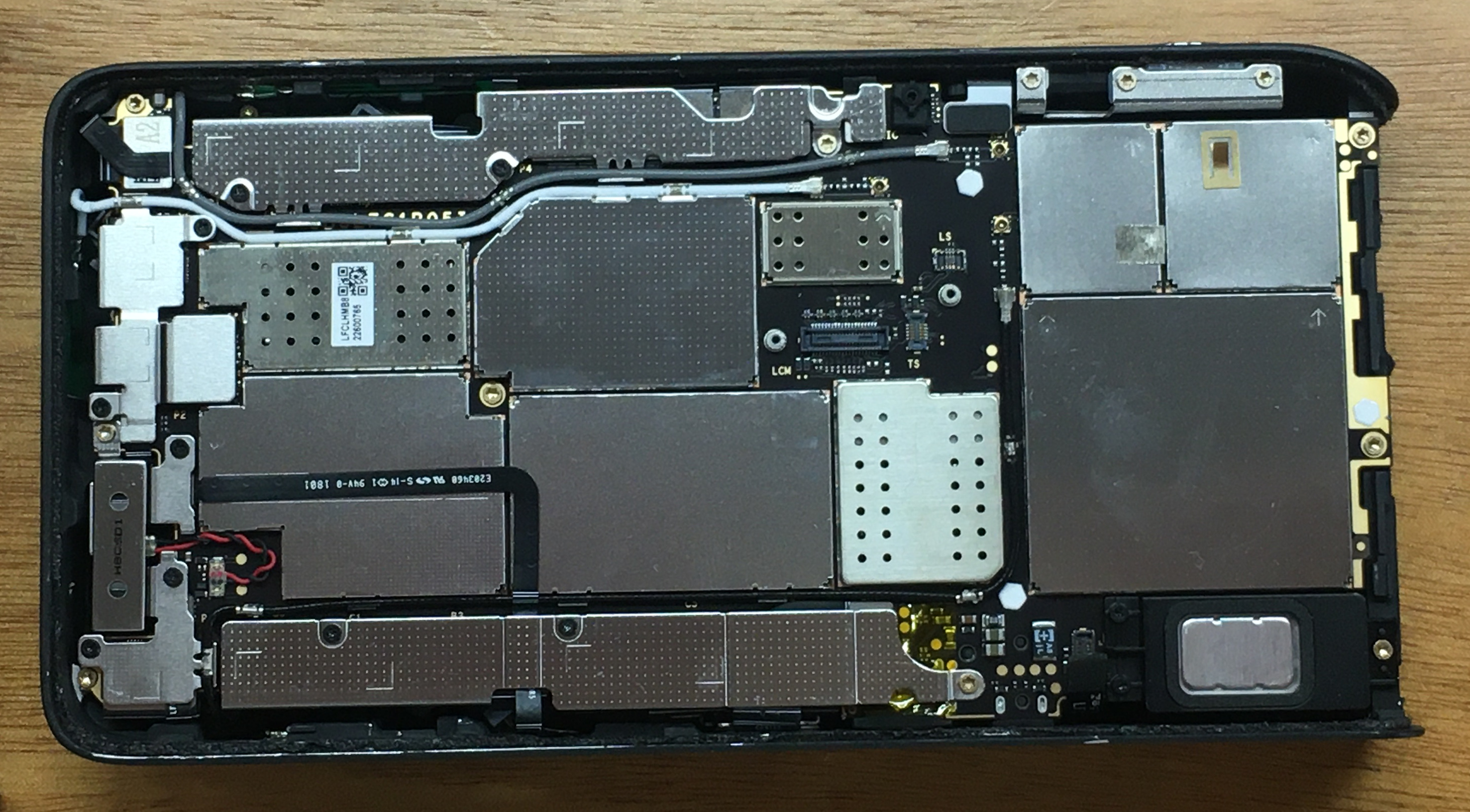
Removing the Main Board
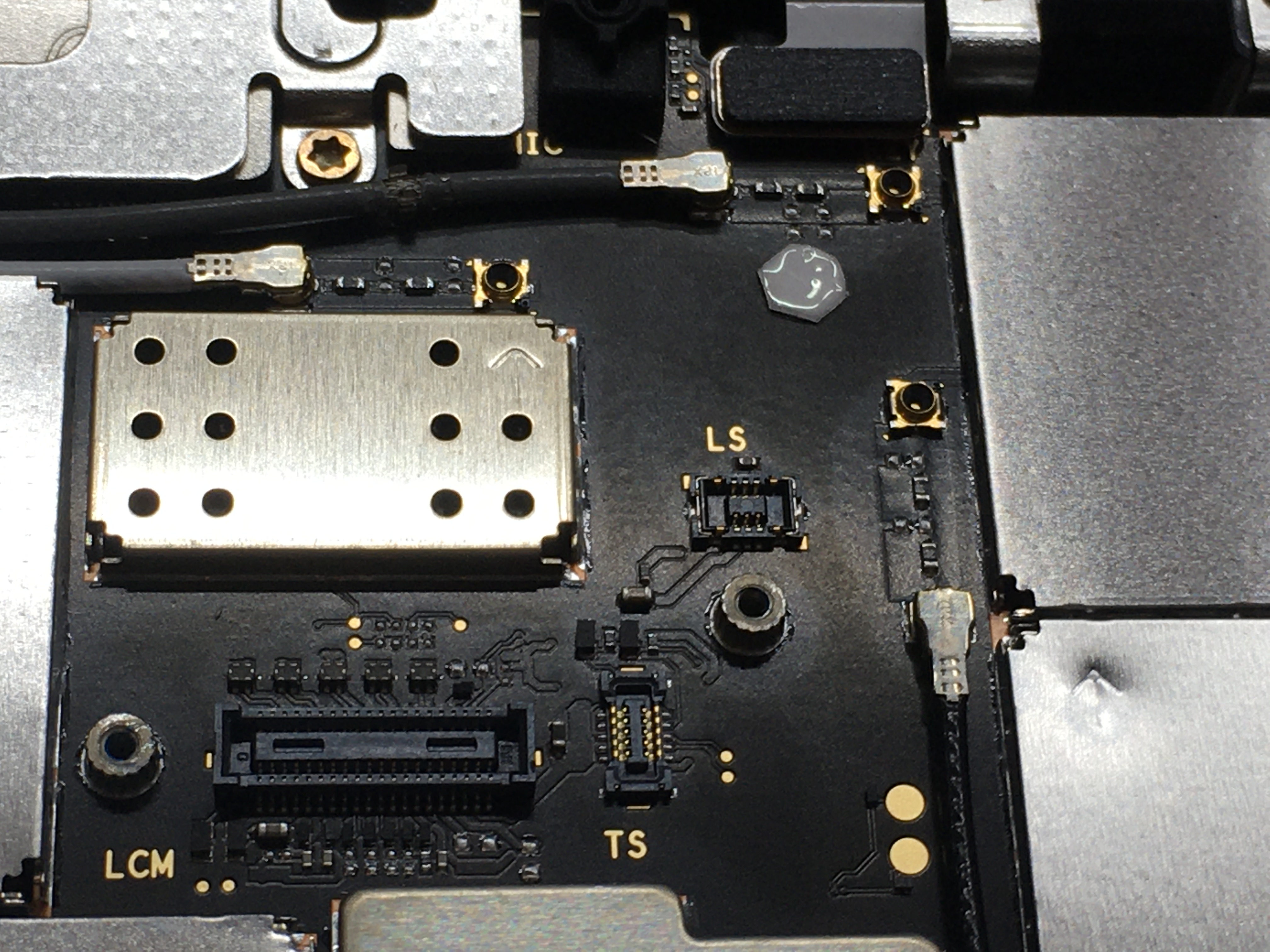
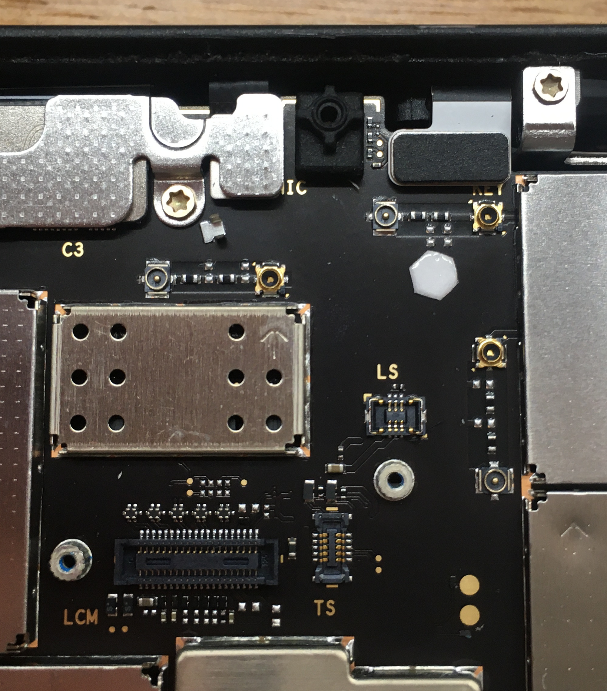
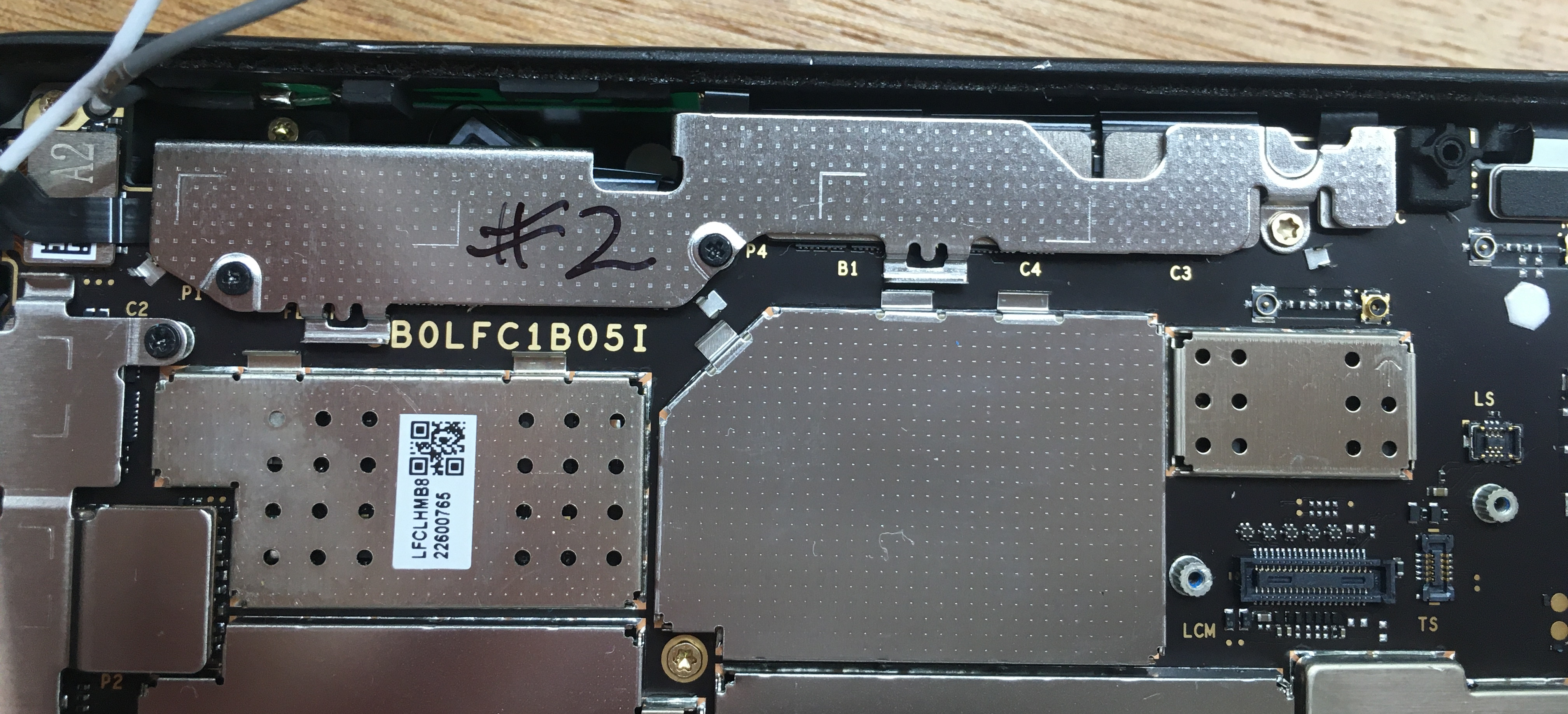
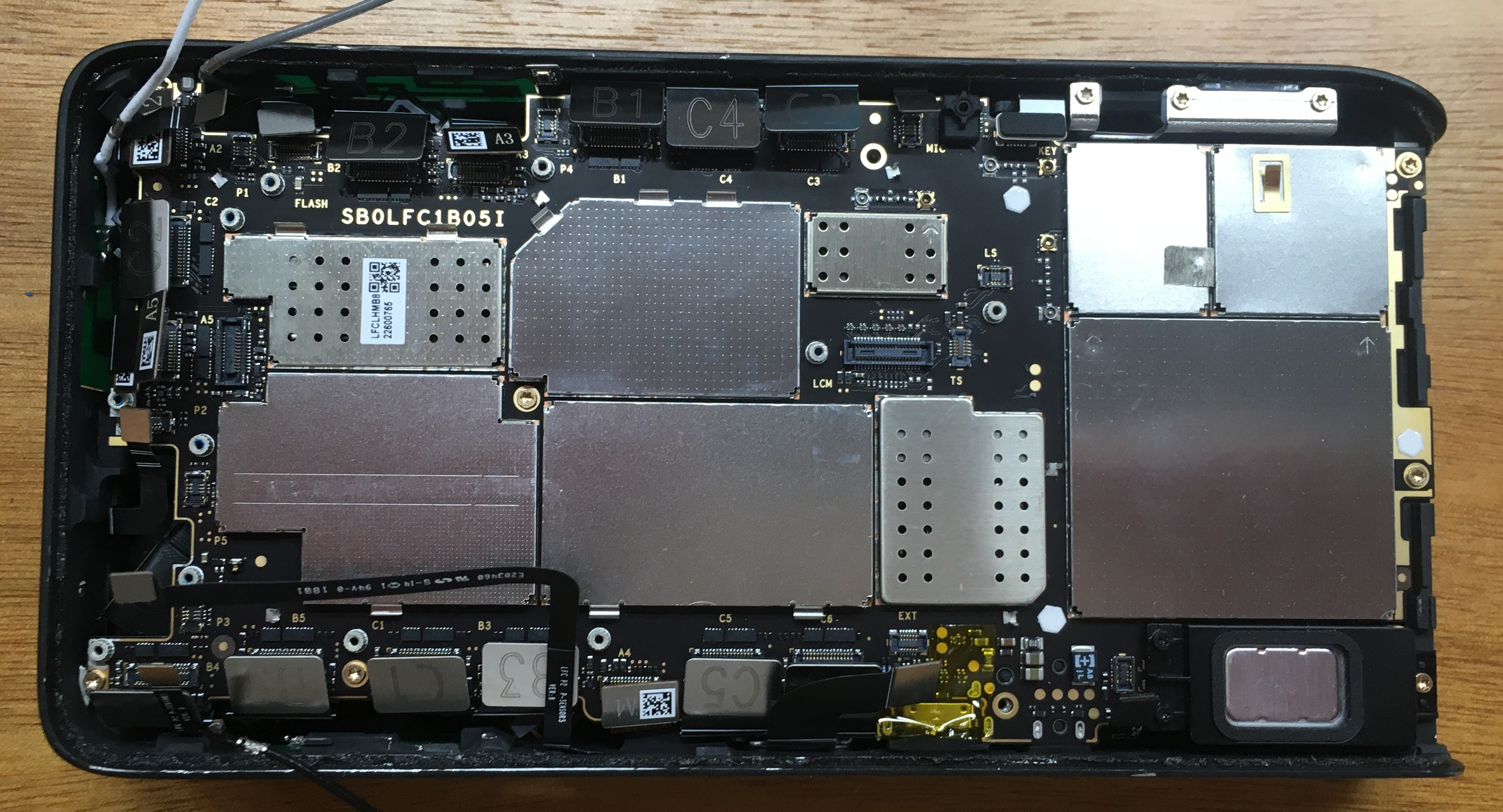
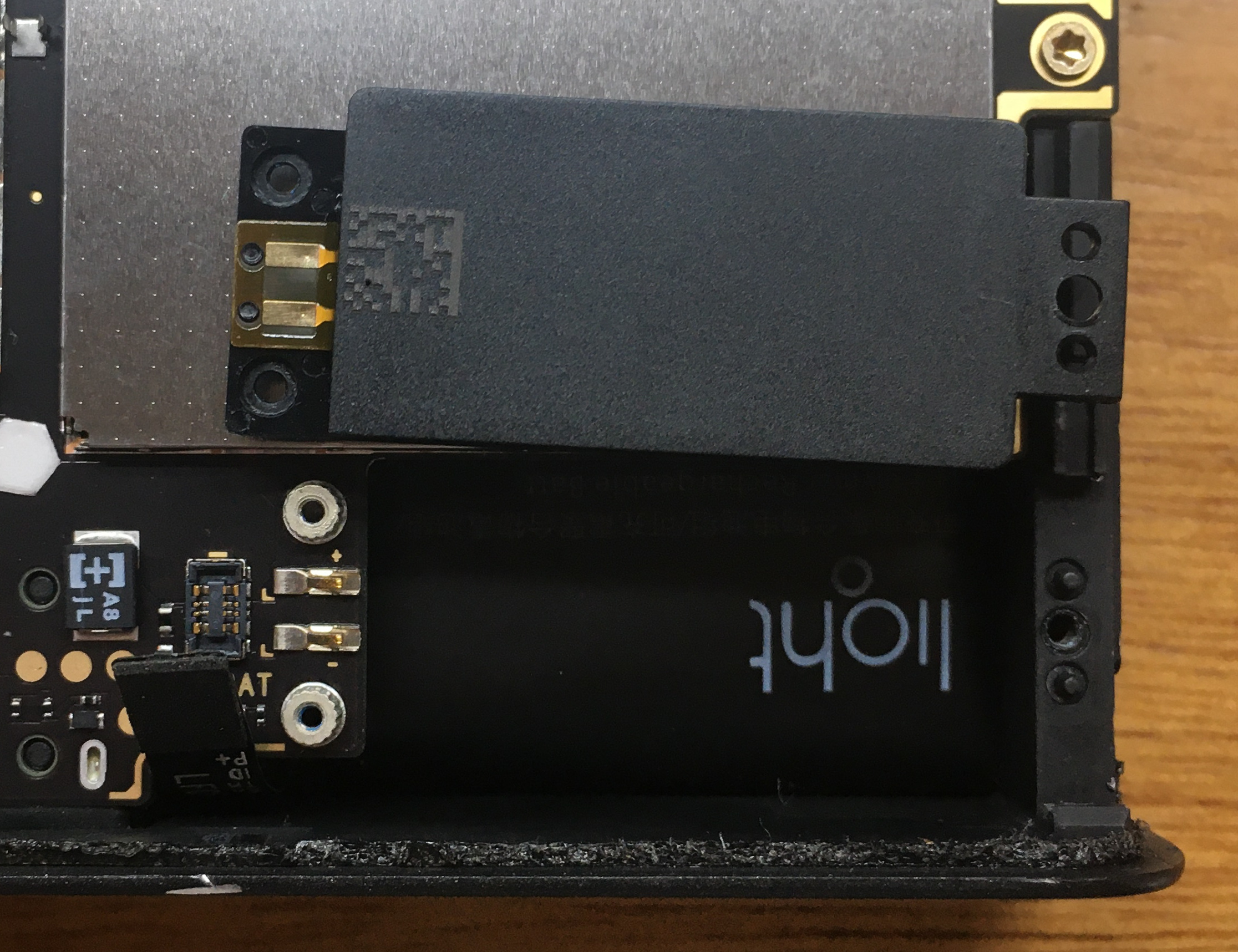
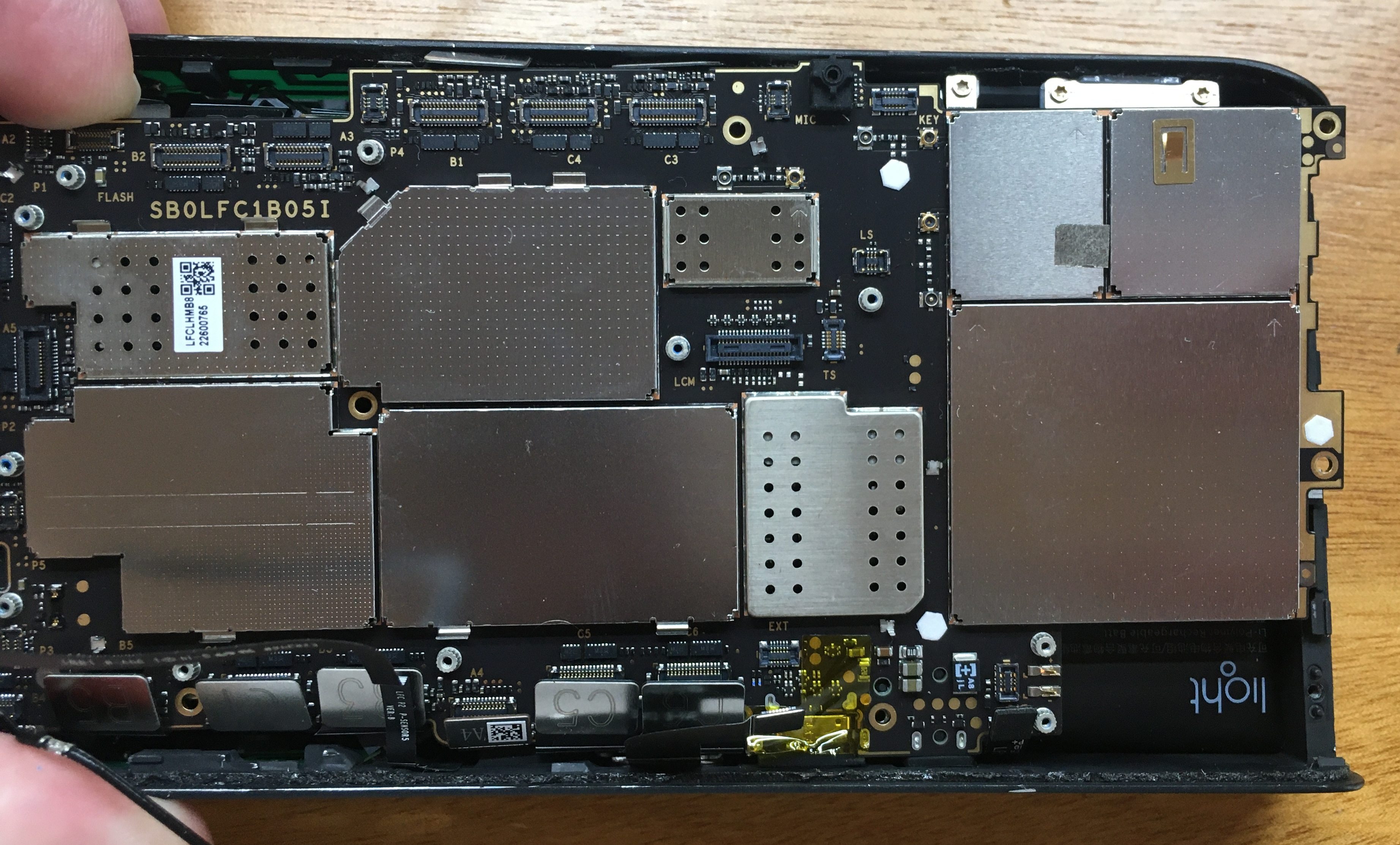
Immediately disconnect the battery. Thankfully, the main board is remarkably well labeled: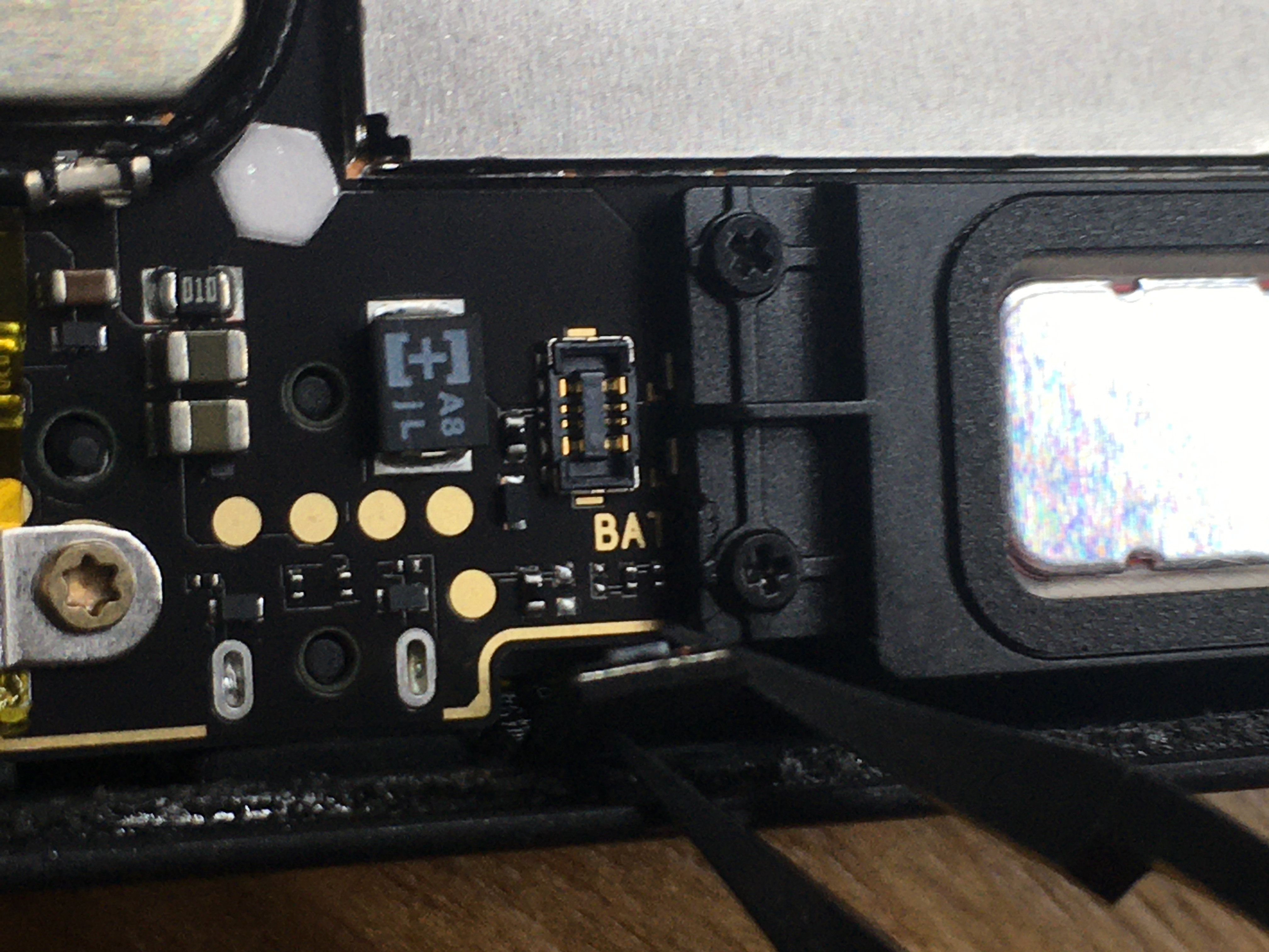
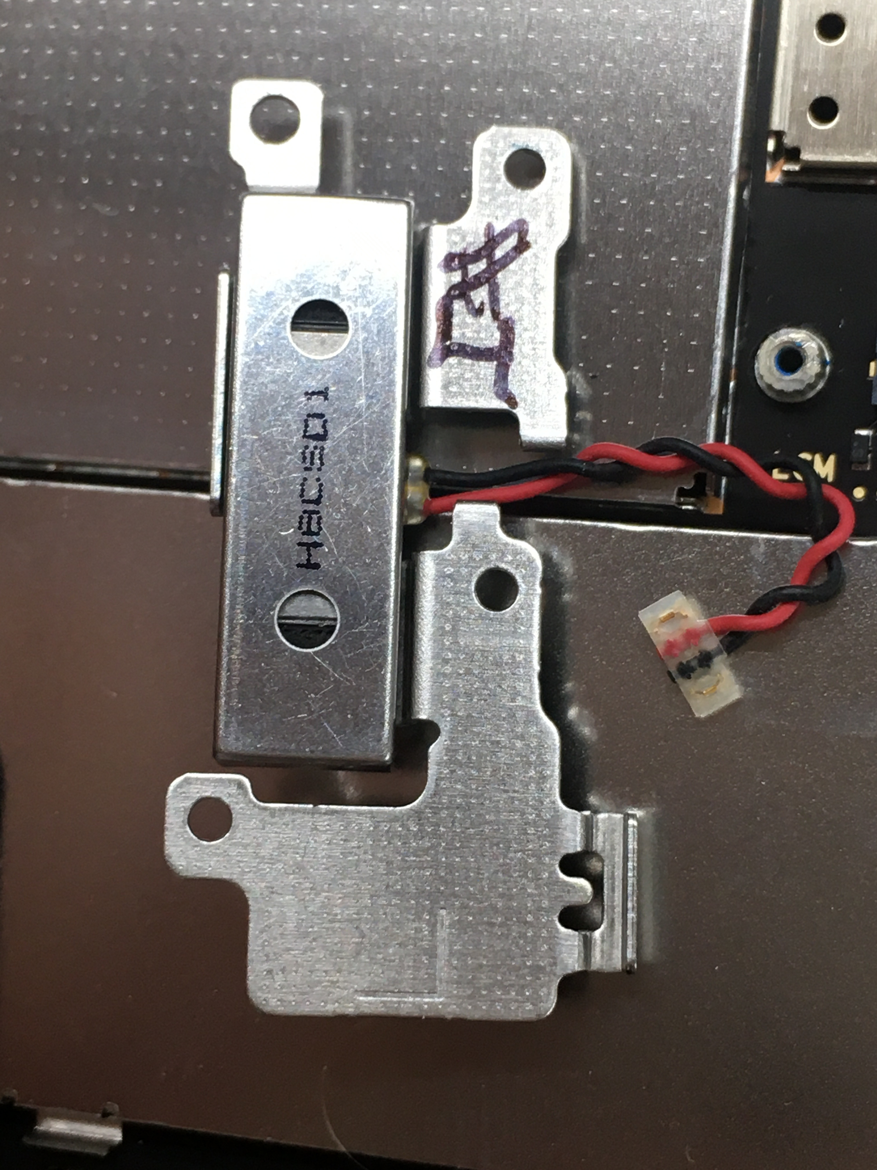
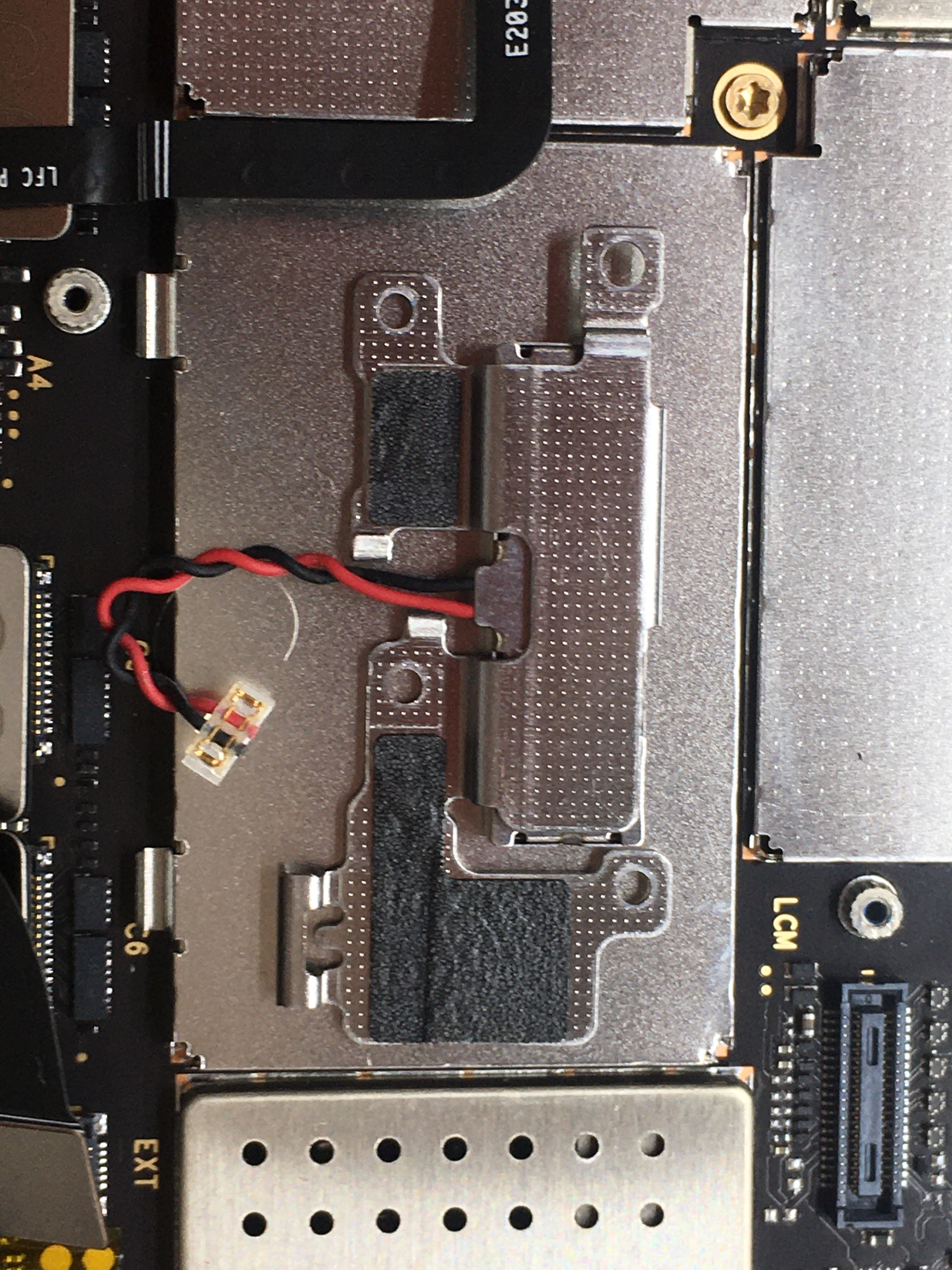
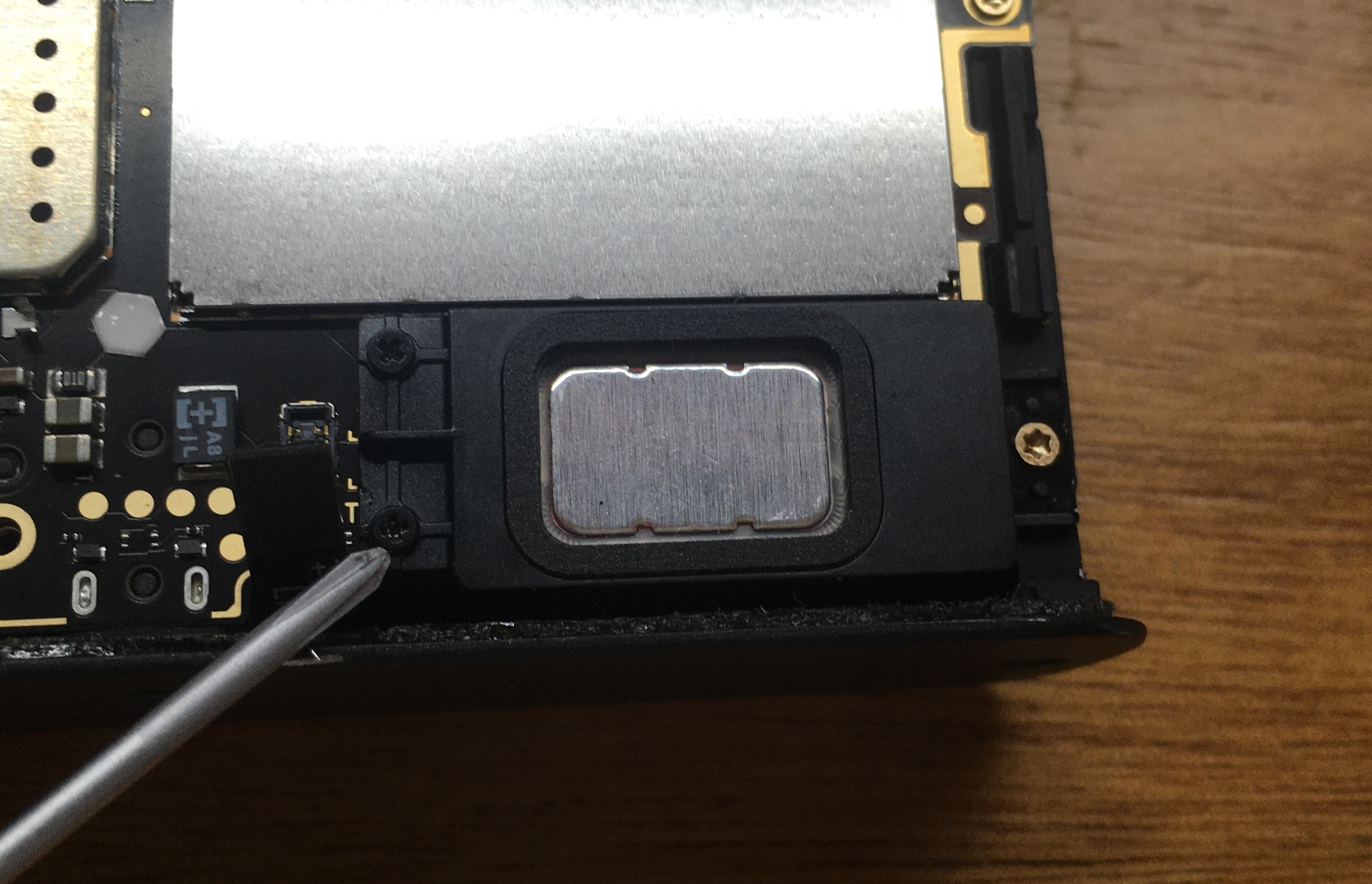
Located bottom-right of the board, next to the speaker(?)
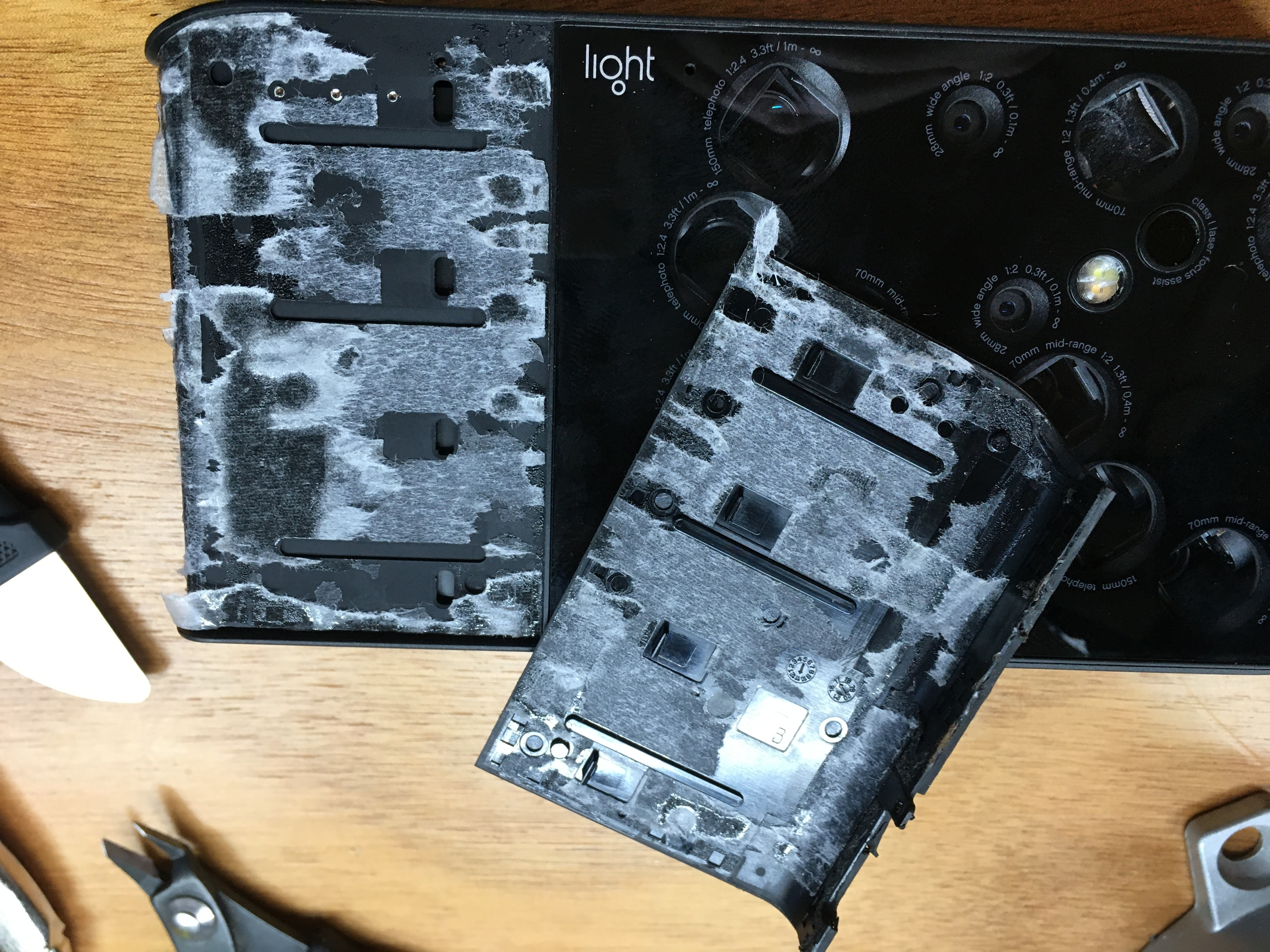
Before and after plate and cables removal
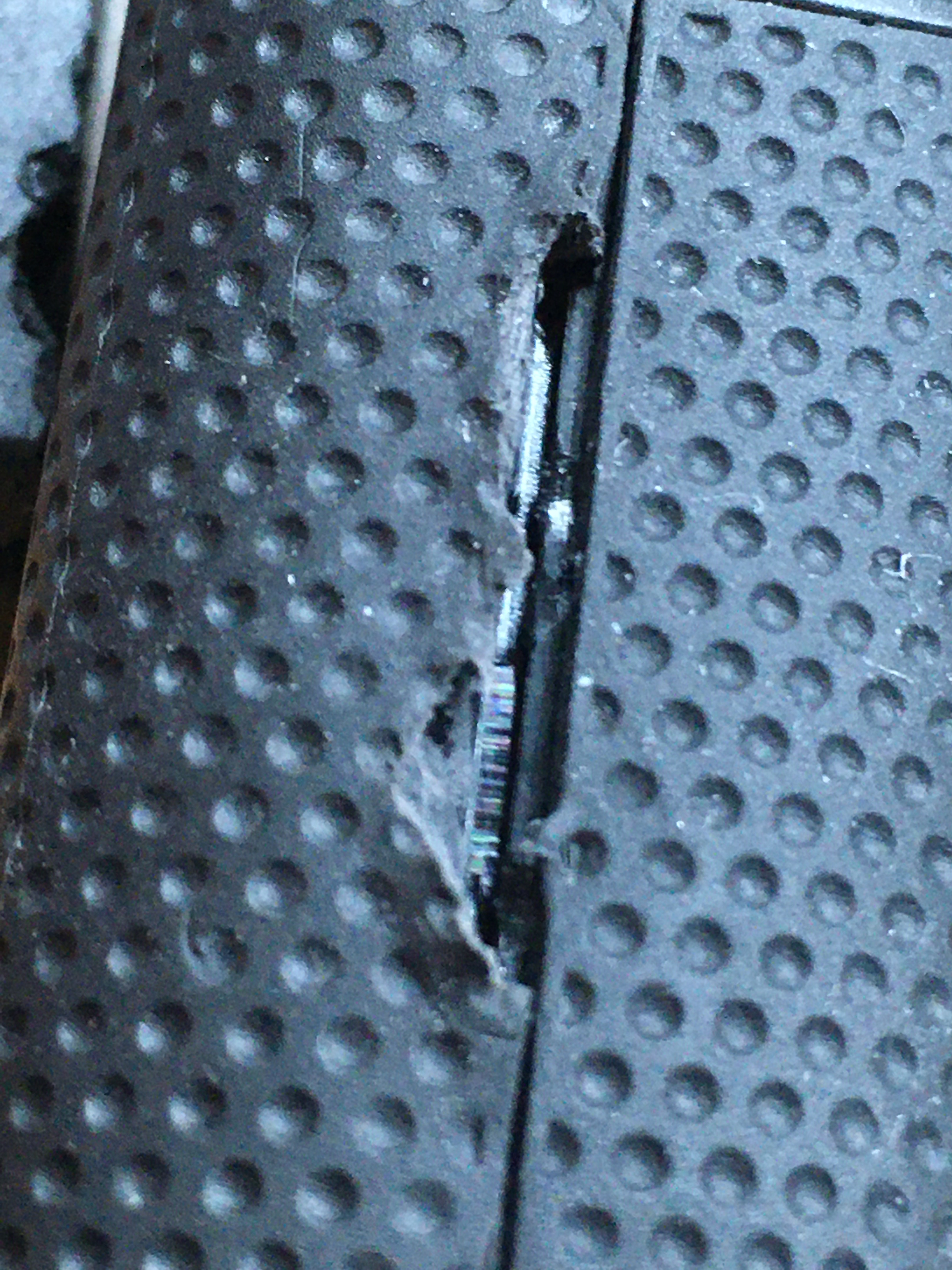
Note the torn cable. 😬️
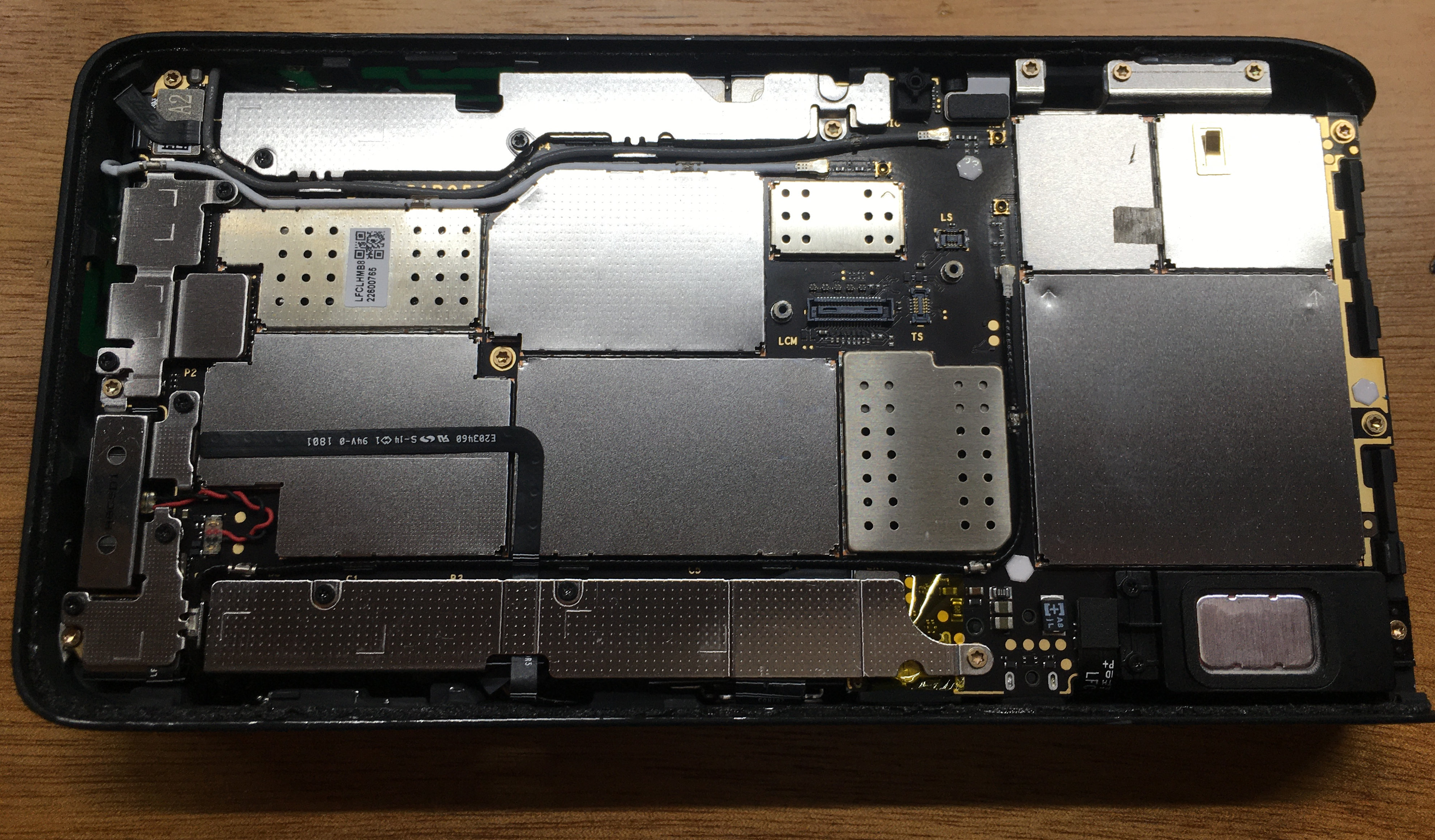
Ignore that the battery is connected in these photos. *shifty eyes*
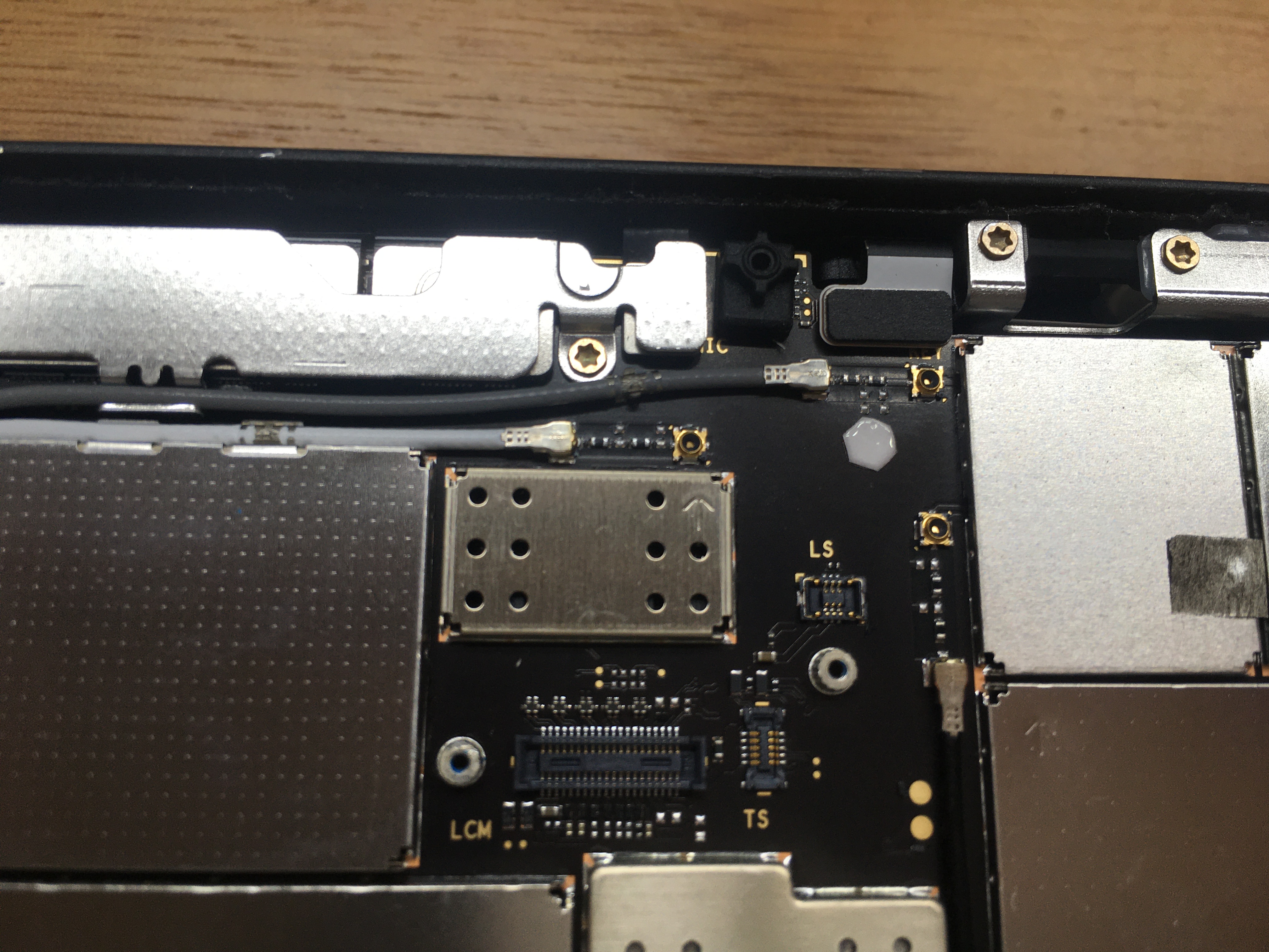
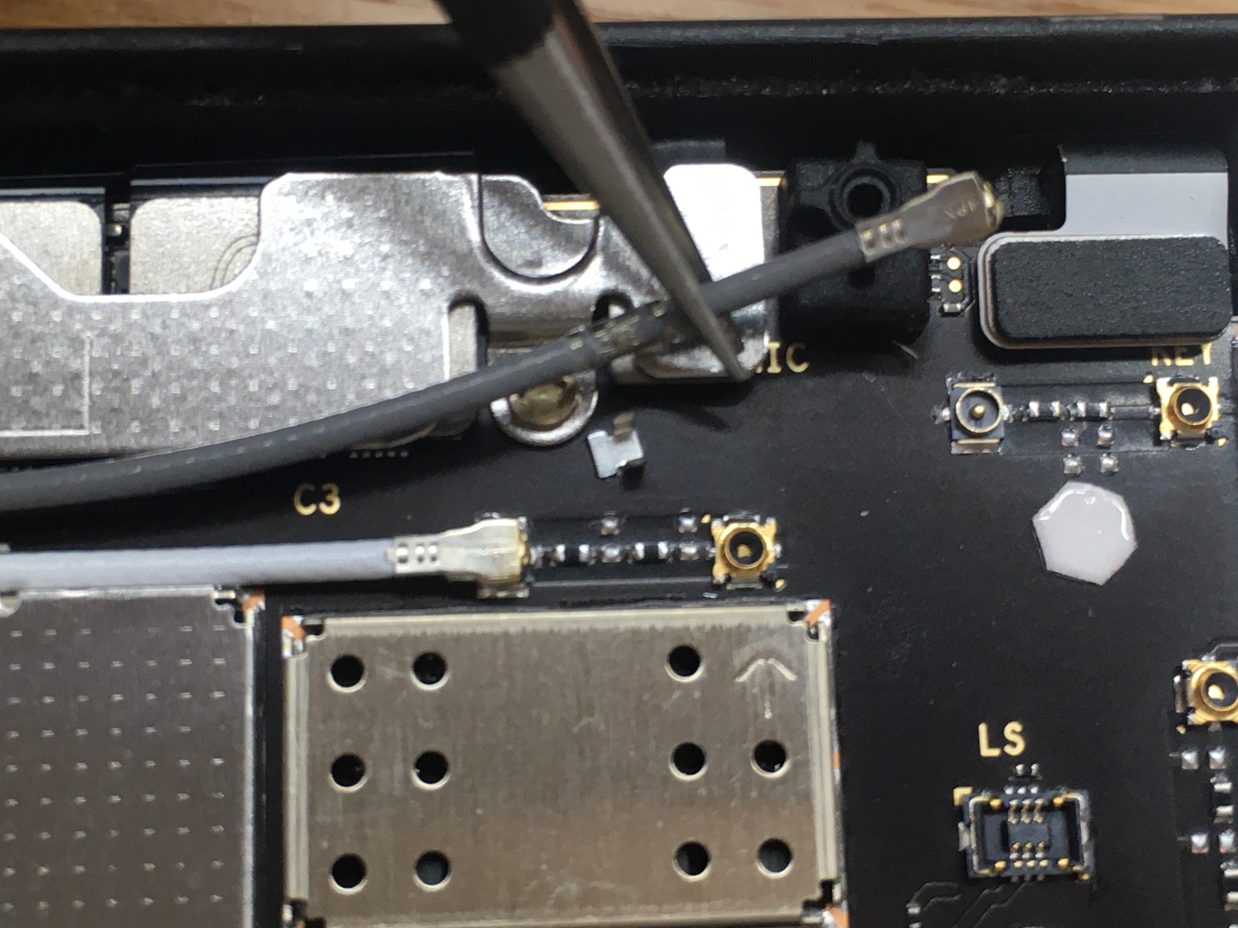
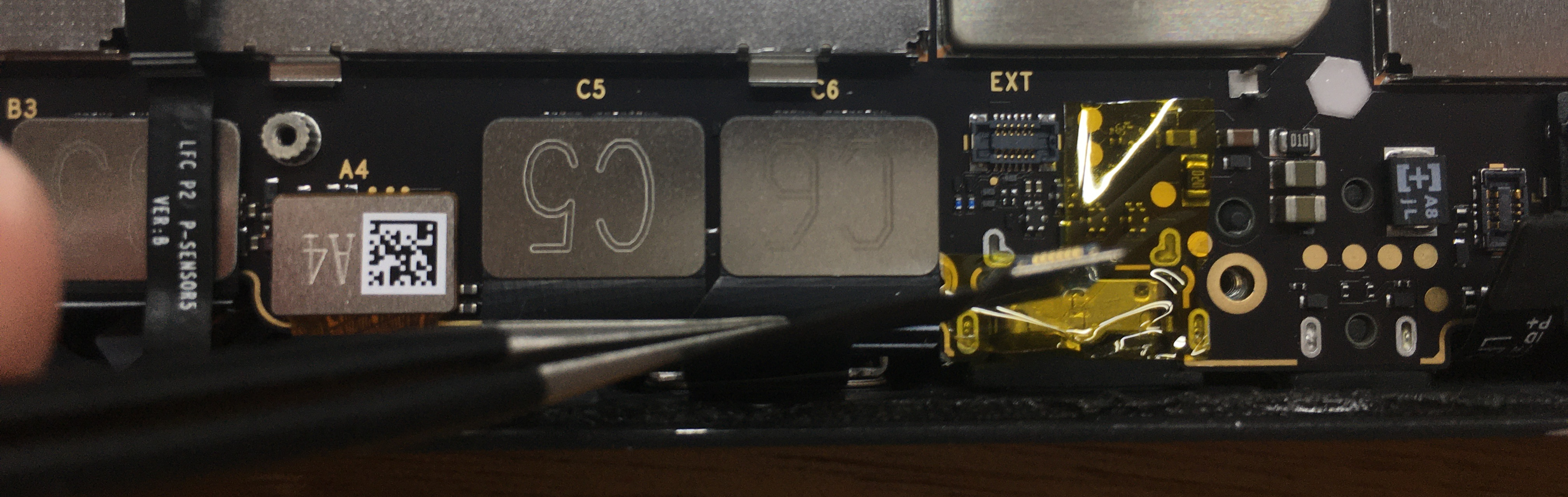
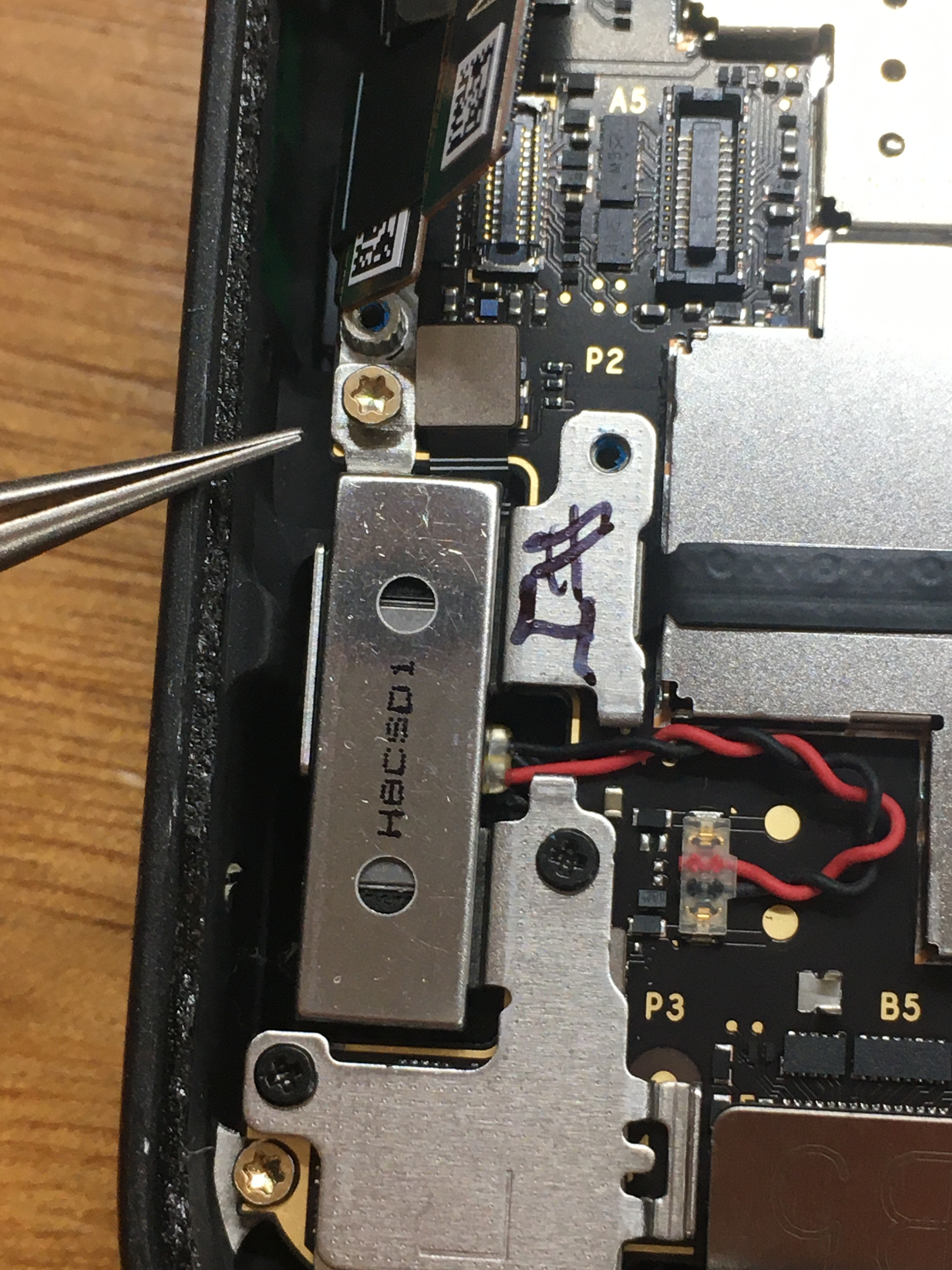
I haven't seen those cable retention clips before.
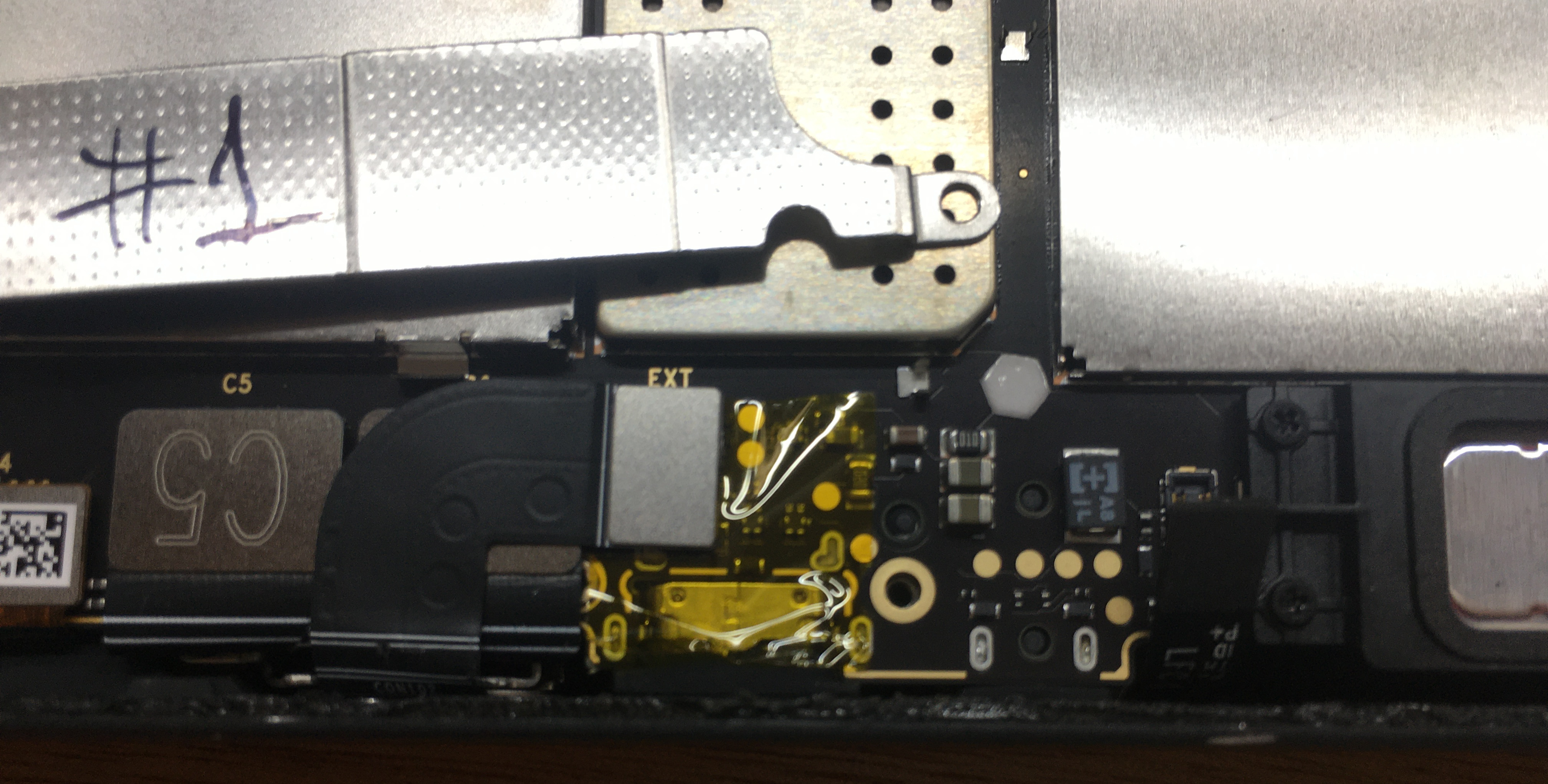
Note the extra micro-coax connectors, in opposite genders. Odd.
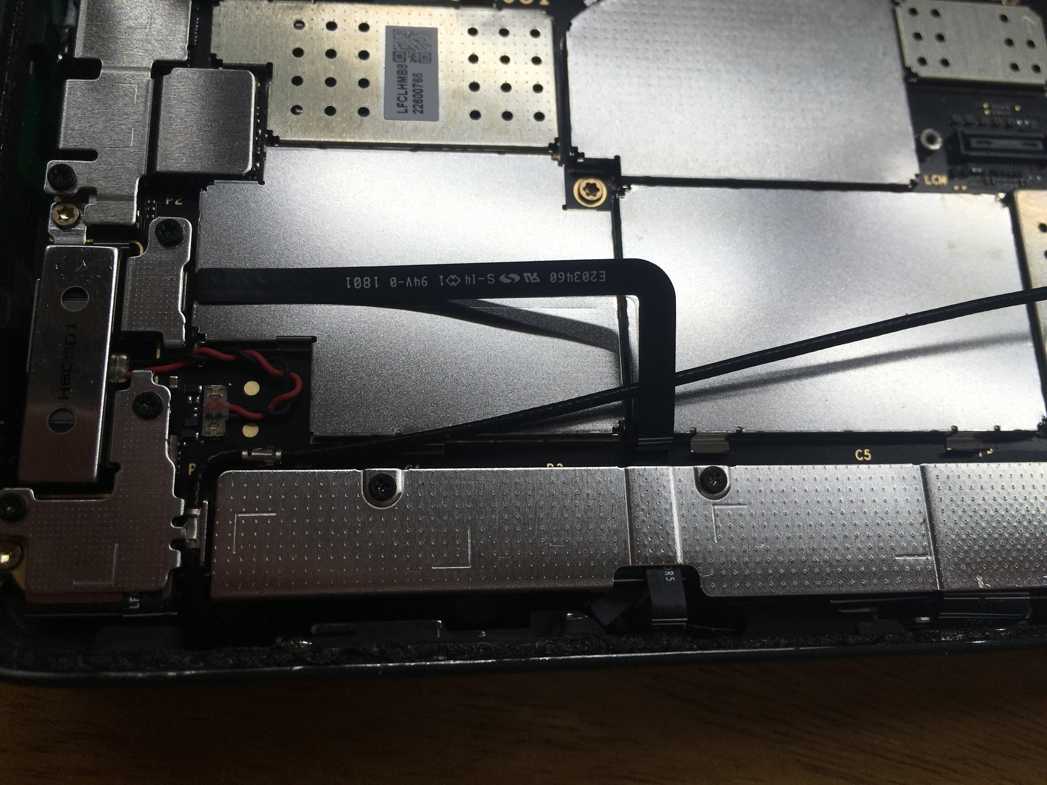
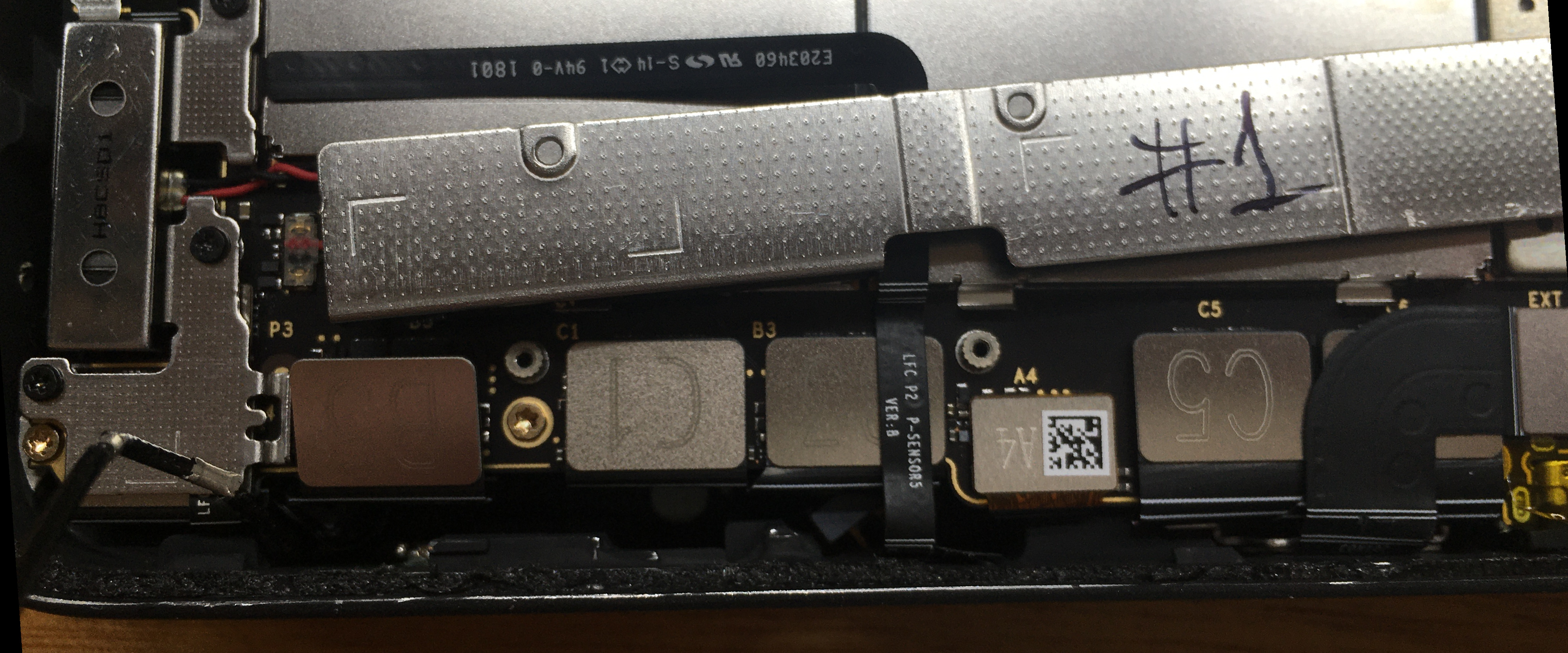
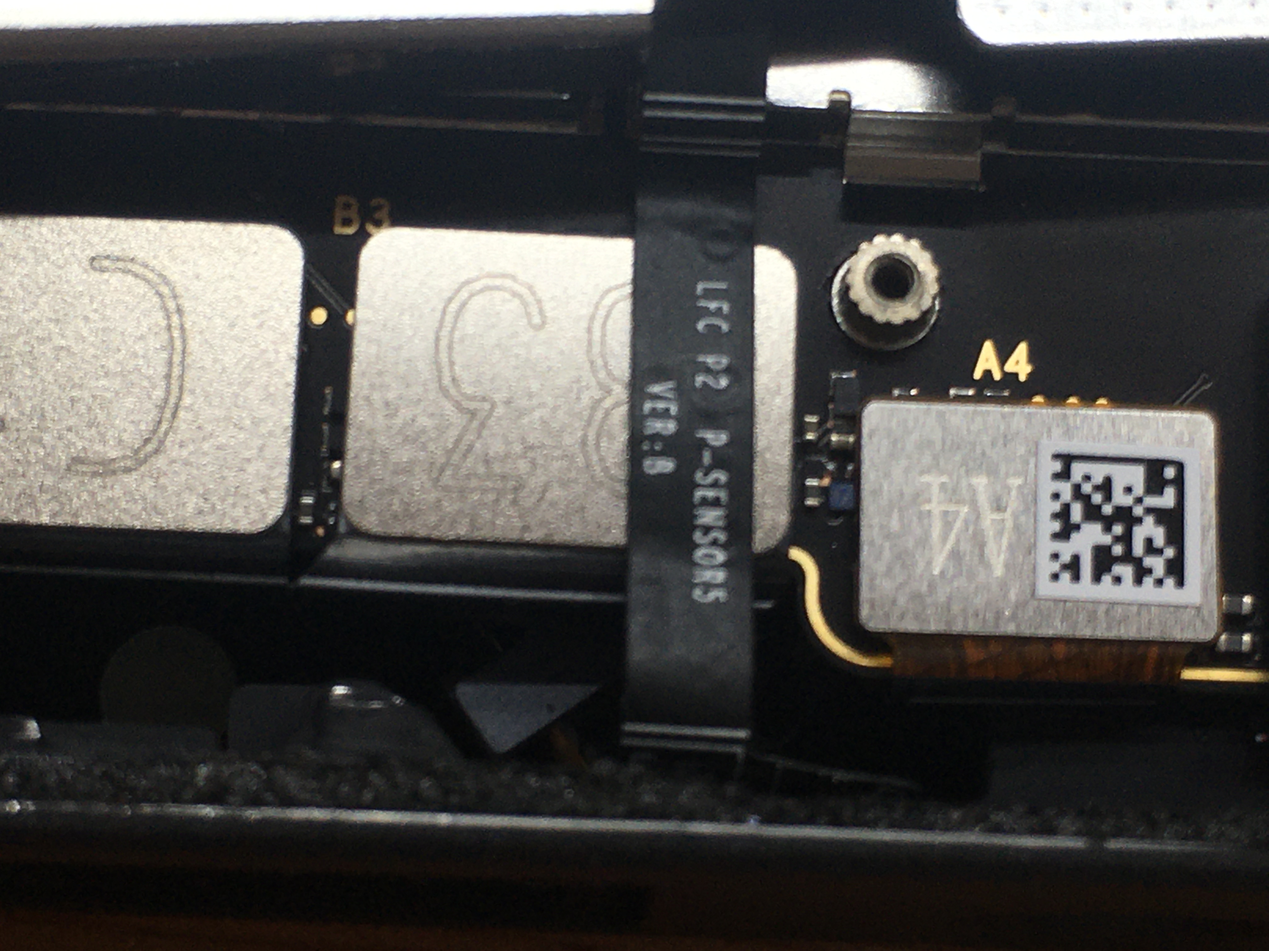
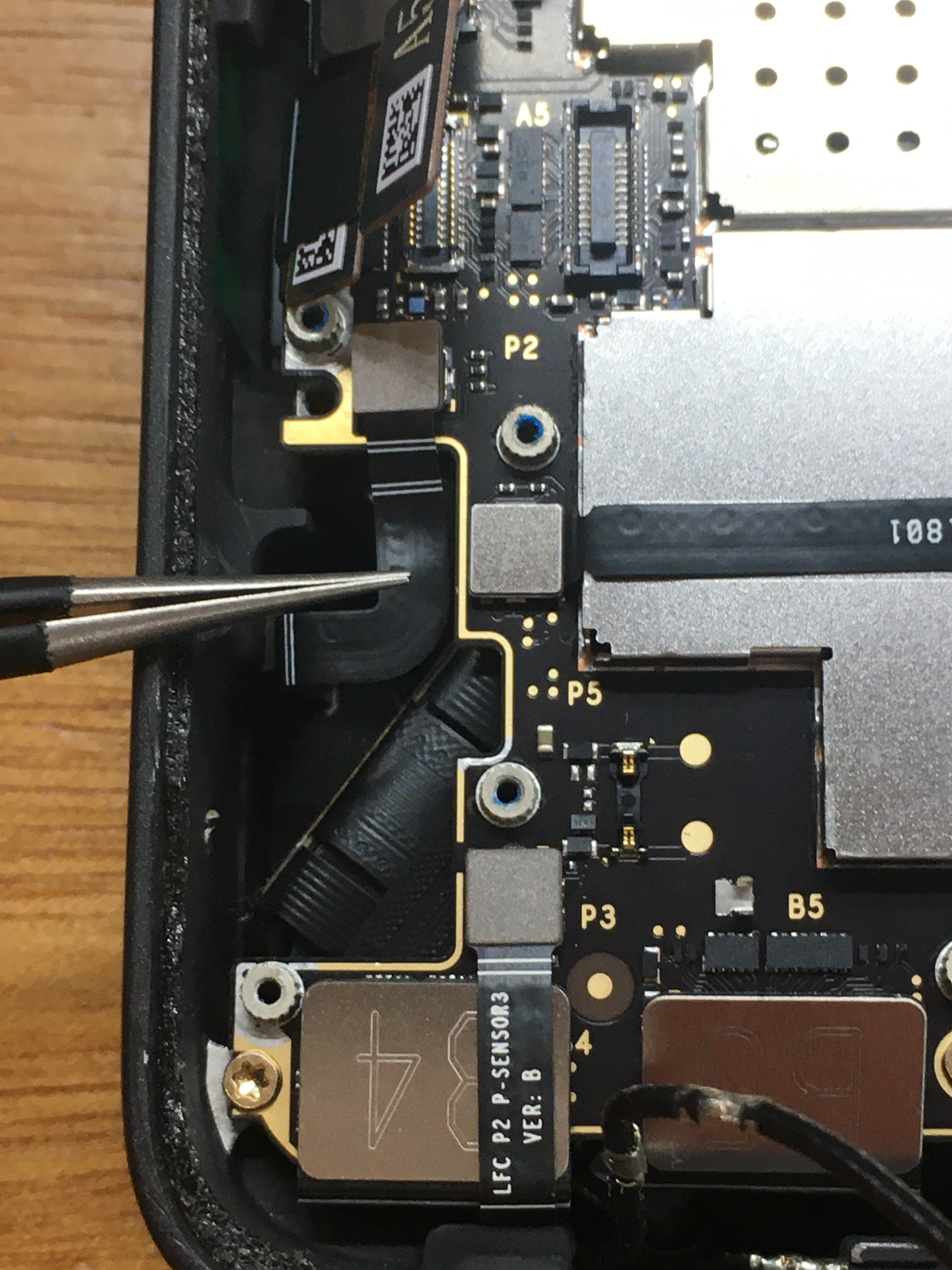
Watch out for this ribbon cable, the coax runs under it, not over.
It covers image sensor connectors A4, B3, B5, C1, C5, and the bottom/external proprietary "Light" connector.
Note the Kapton/polymide tape. Last minute insulation, I assume.
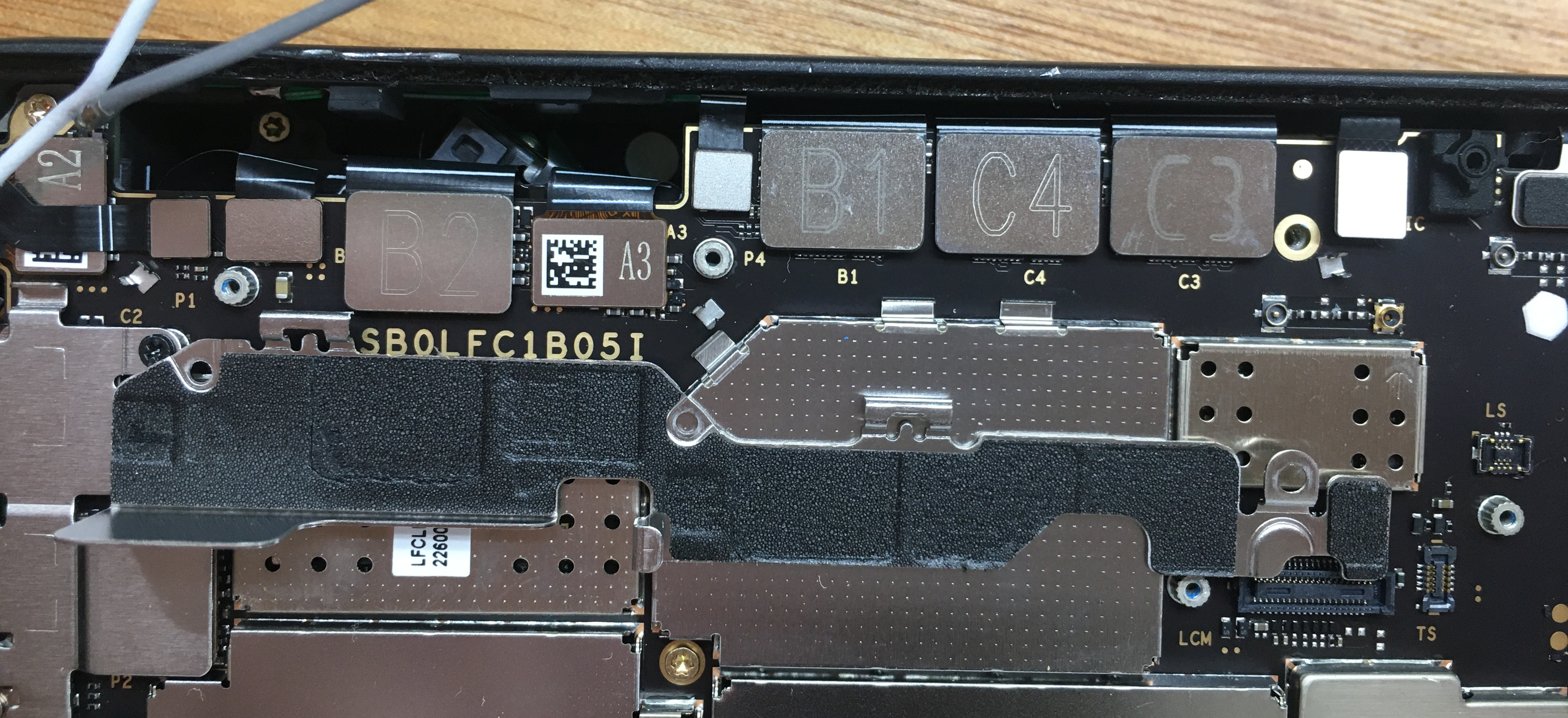
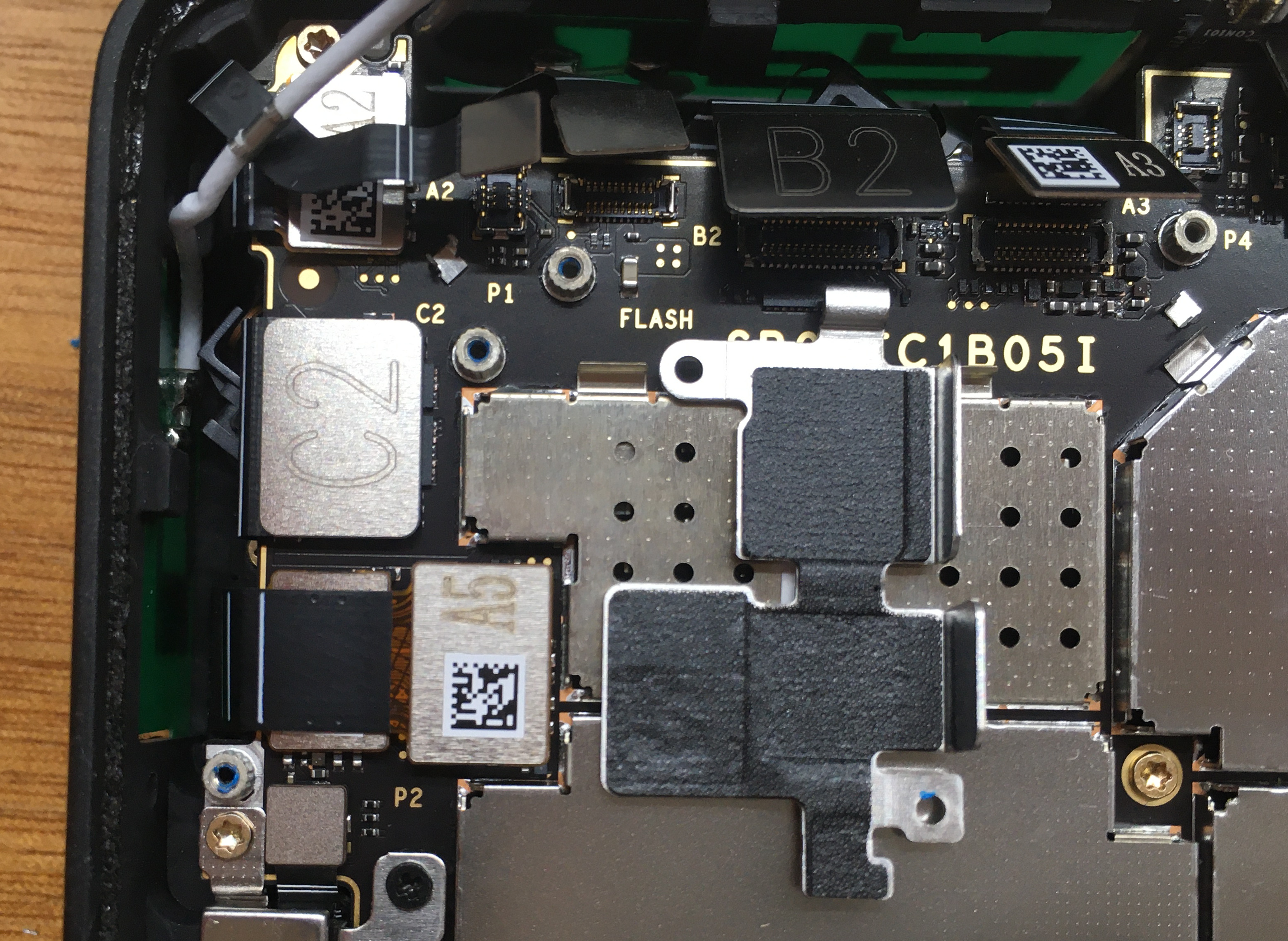
It covers image sensor connectors A2, A3, B1, B2, C3, C4, and several other unlabeled connectors.
The padding under the plate is slightly sticky,
it may lift connectors when the plate is removed..
It covers image sensor connectors A1, A5, and C2.
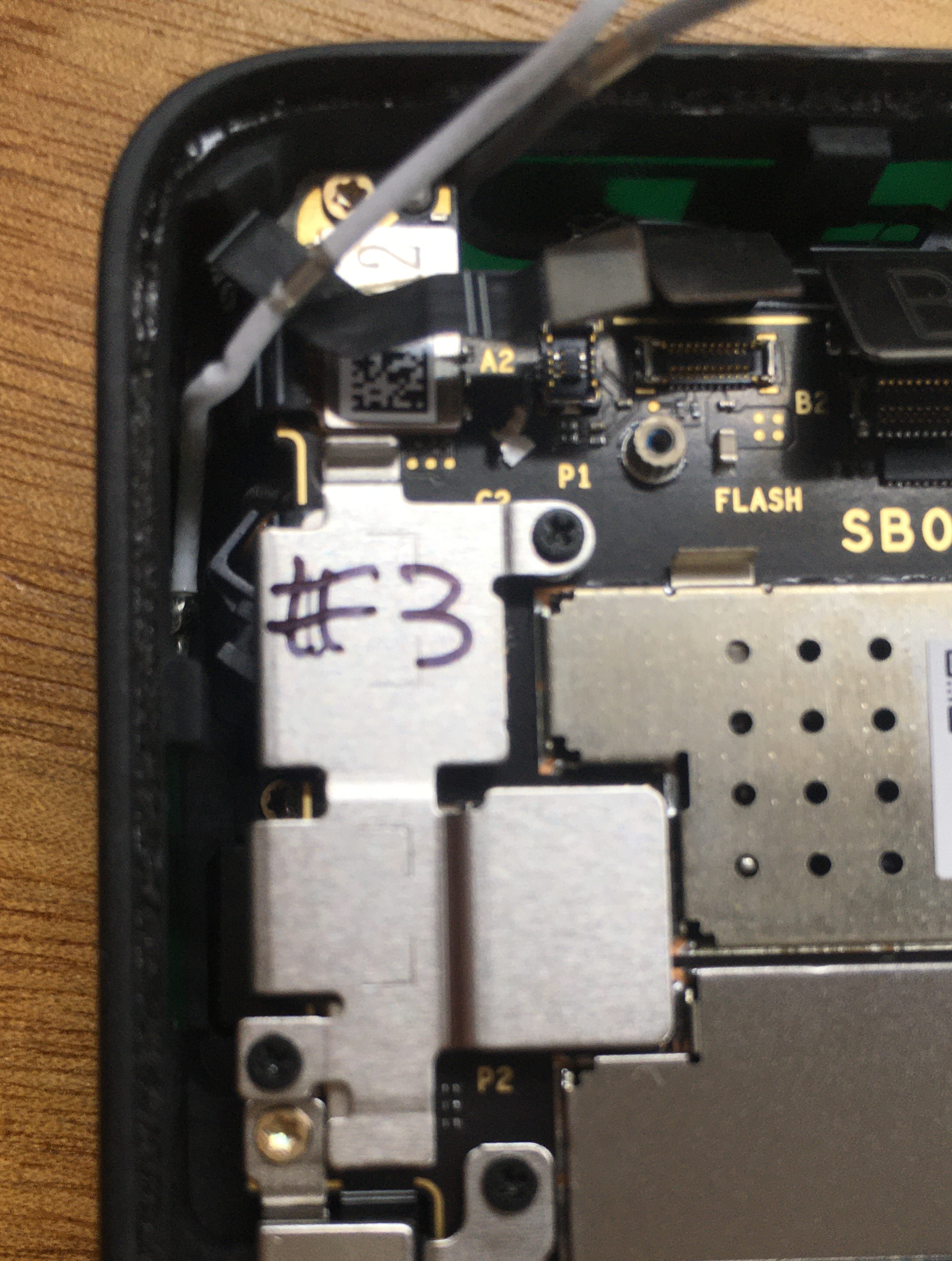
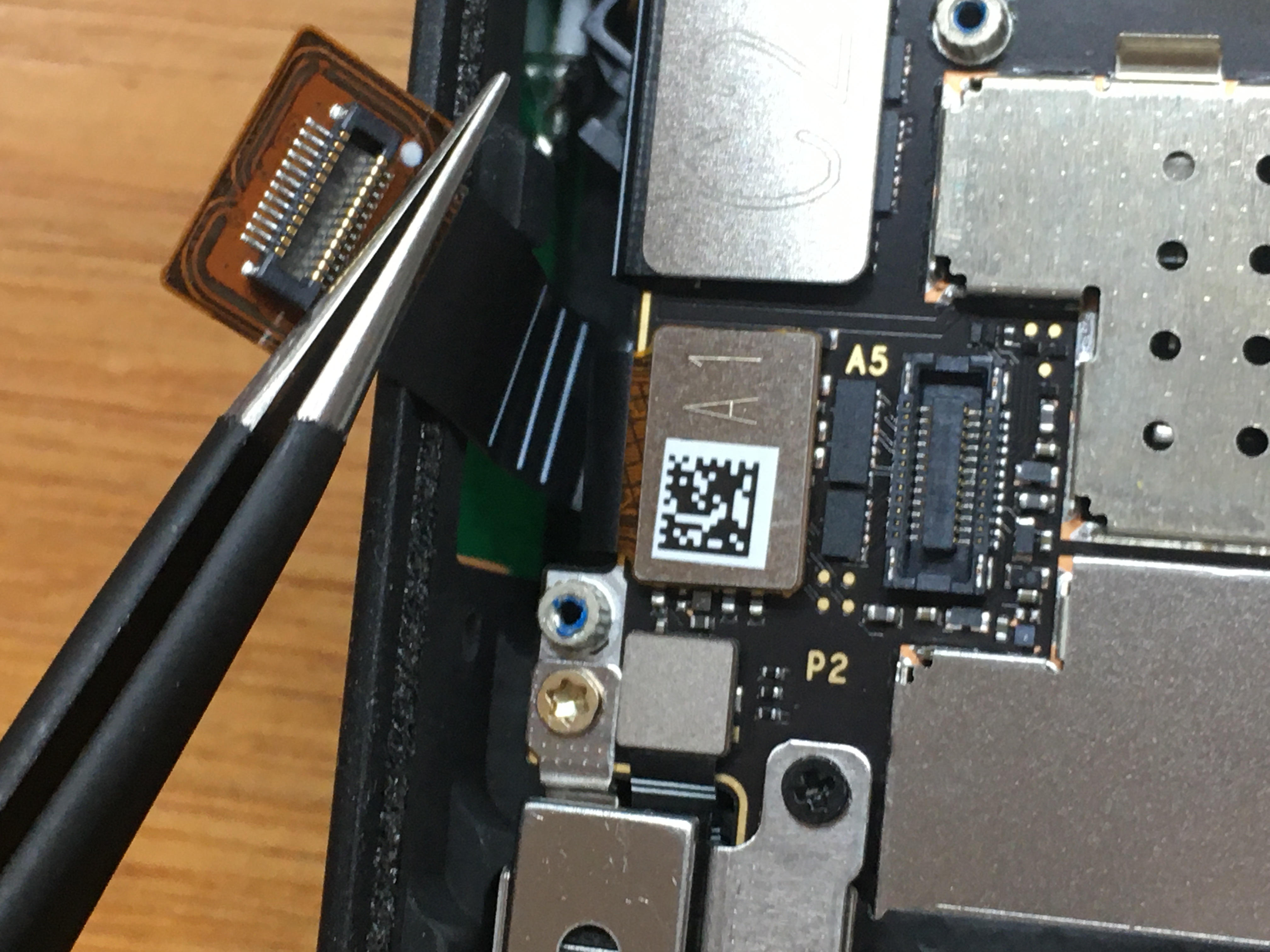
Note that A1 is under the A5 flex cable.
It covers three unlabeled flex cable connectors and image sensor connector B4.
Note that B4 is under a flex cable.
Motor detail. It's magnetic, and will collect screws.
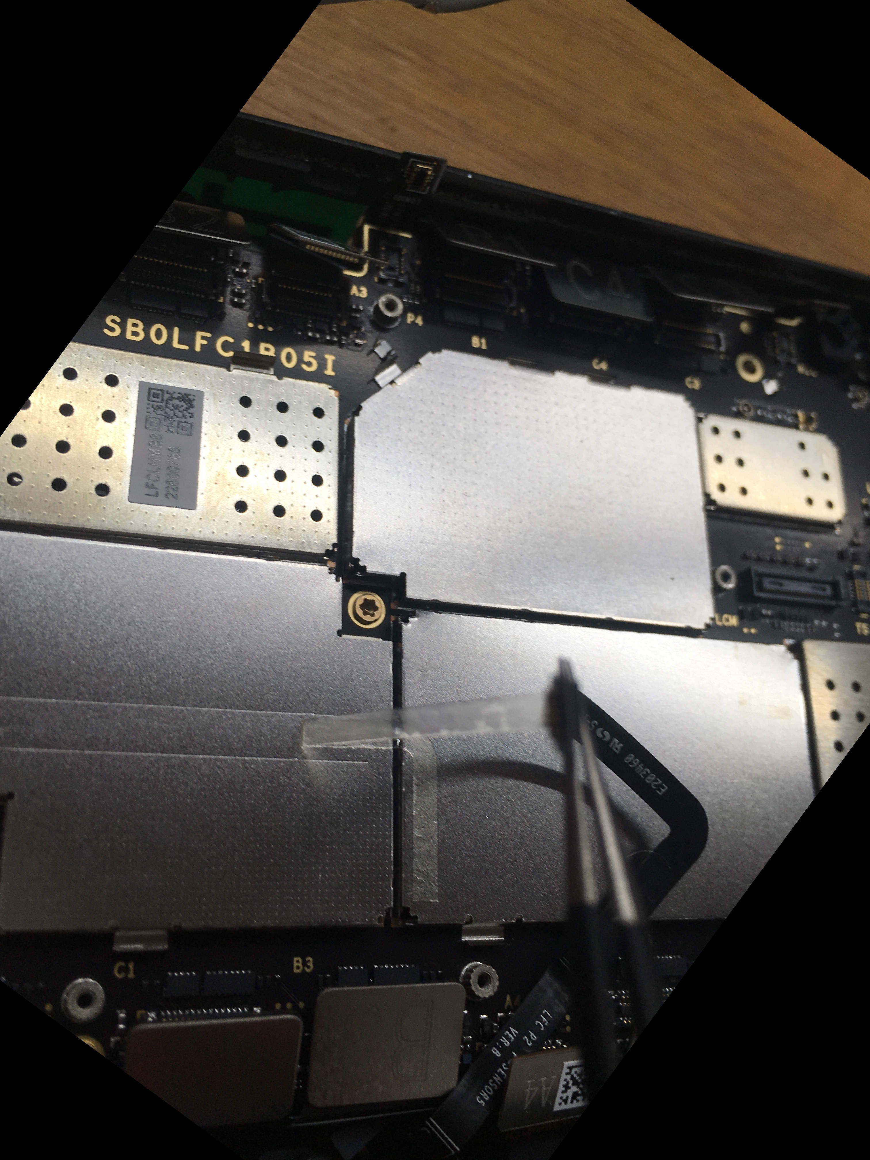
Several of the plate retention screws are actually main board fixture screws, while the rest are simple Phillips screws.
All flex cables disconnected.
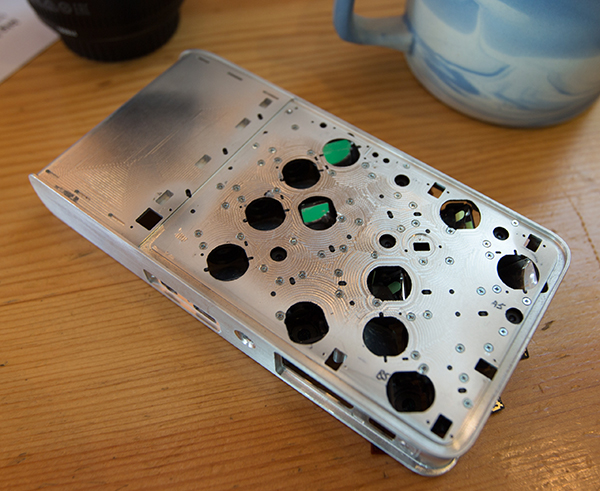
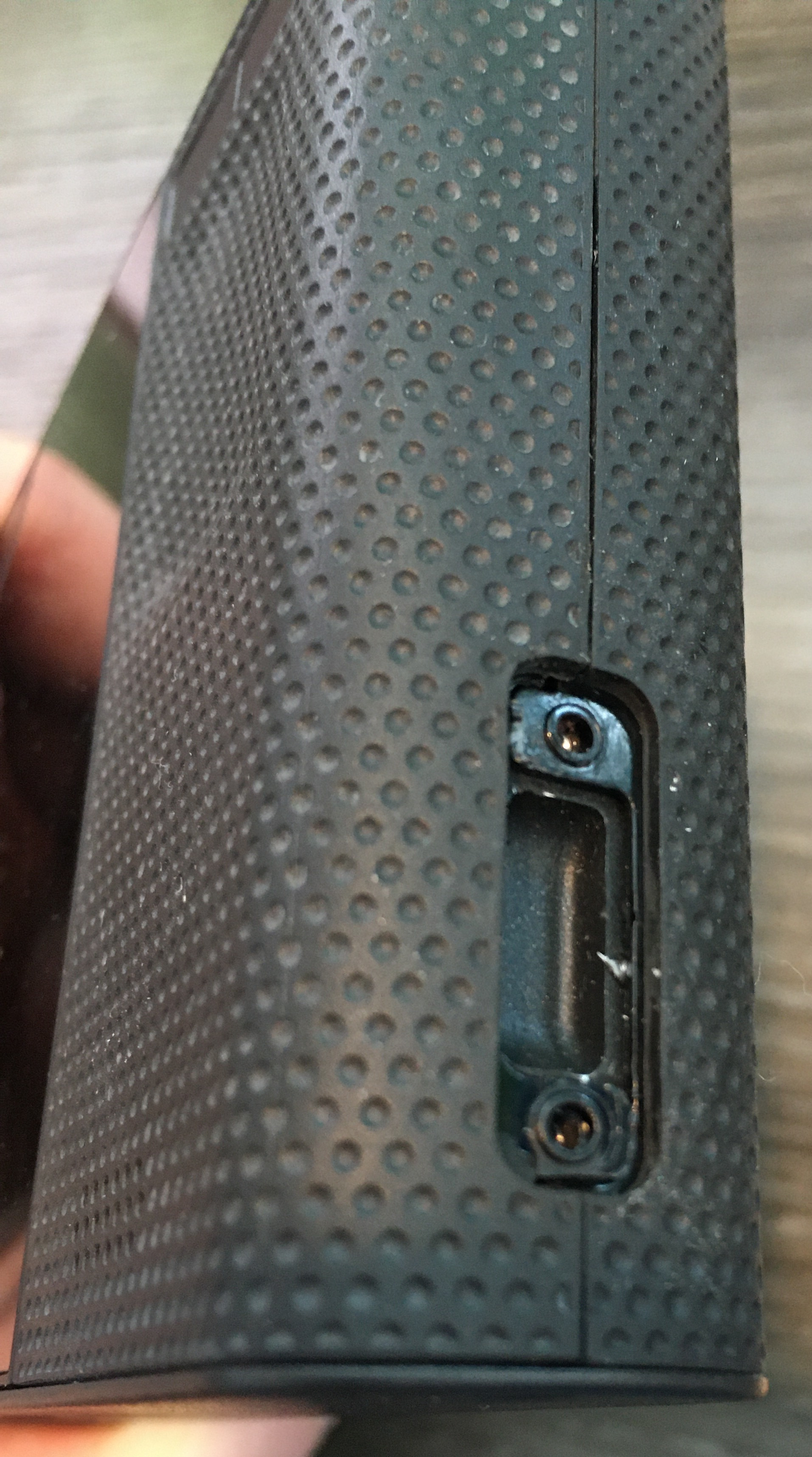
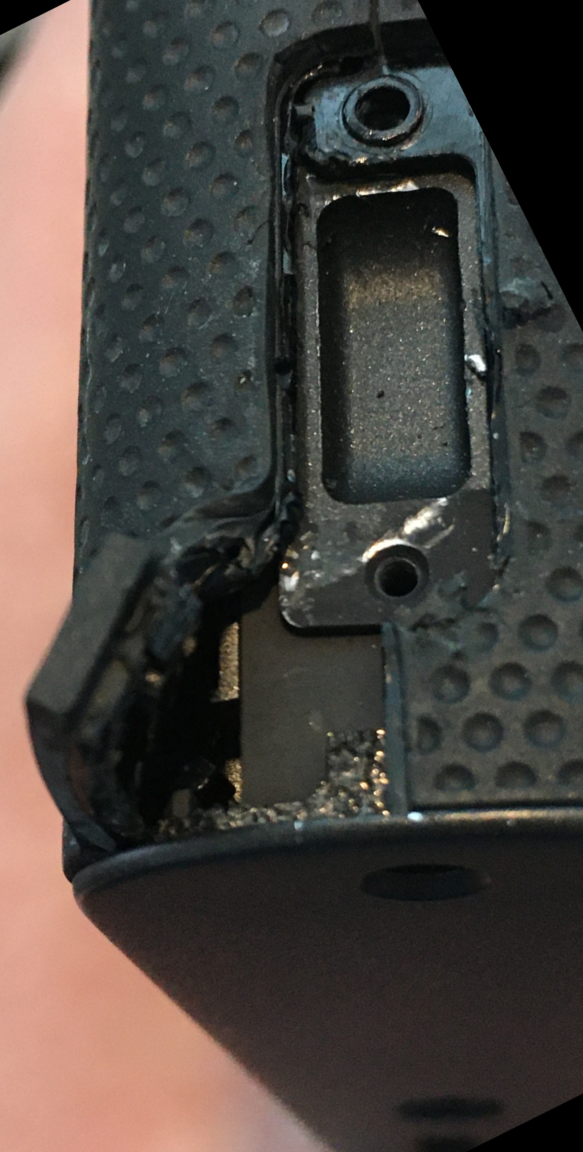
The bottom edge has the USB-C socket extending into the aluminum chassis, so it can't be lifted out vertically.
Be wary of all the connectors - they'll be acting like little springs and will catch on everything.
Lift at the top, pull upwards and out.
High Res Photos
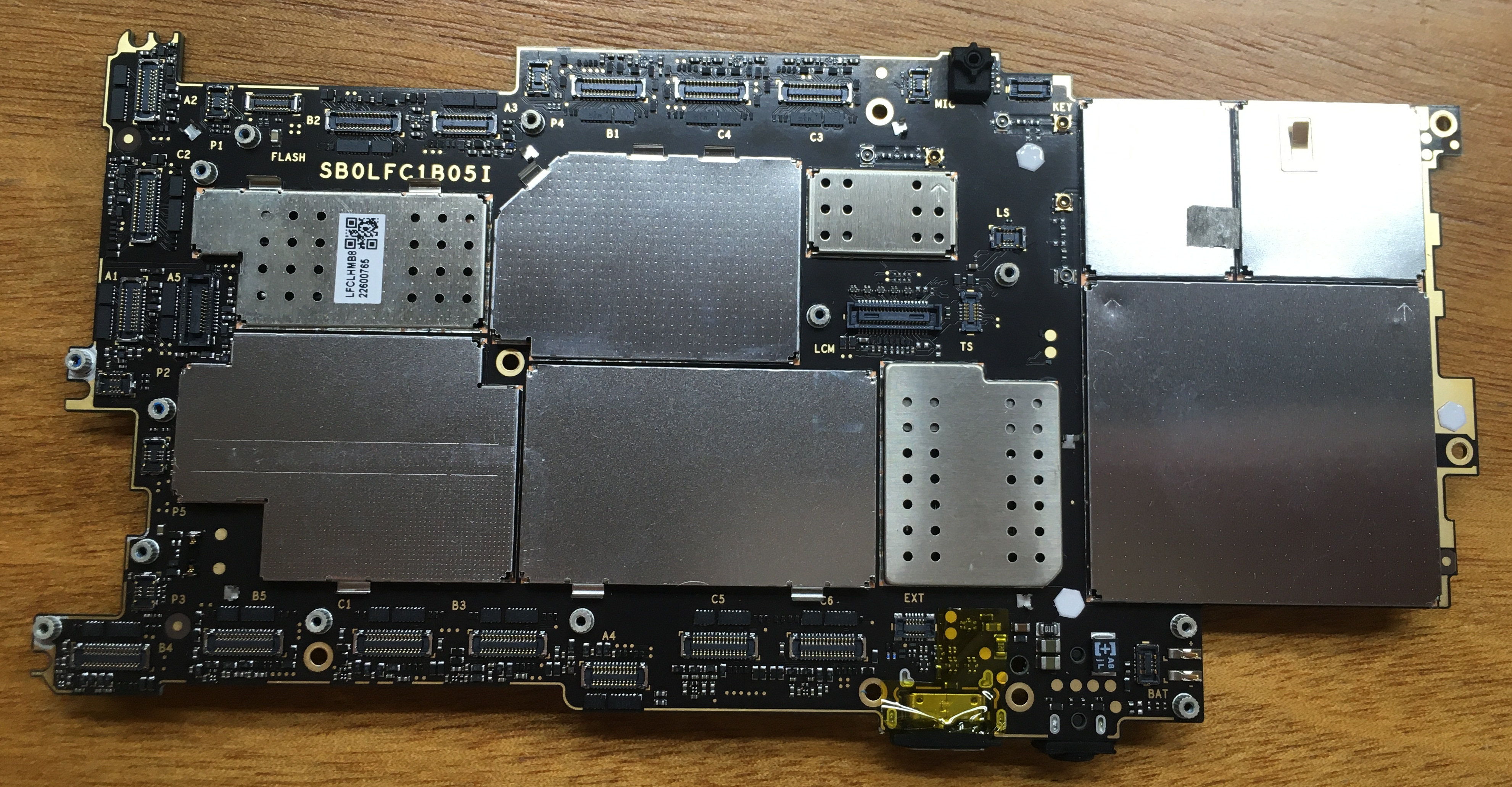
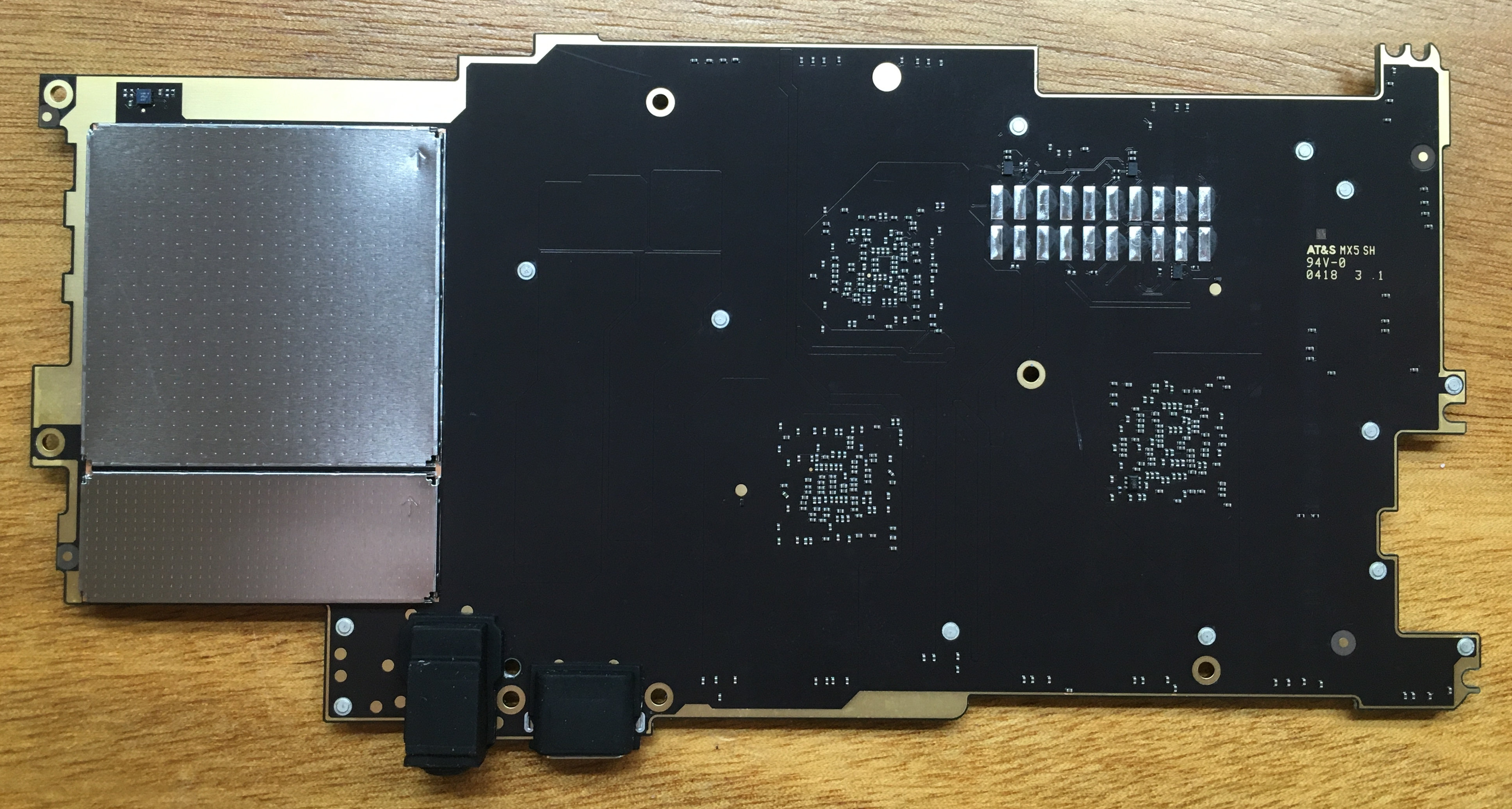
Only the finest iPhone shots.
Note the giant JTAG TAP port pads on the back of the PCB.
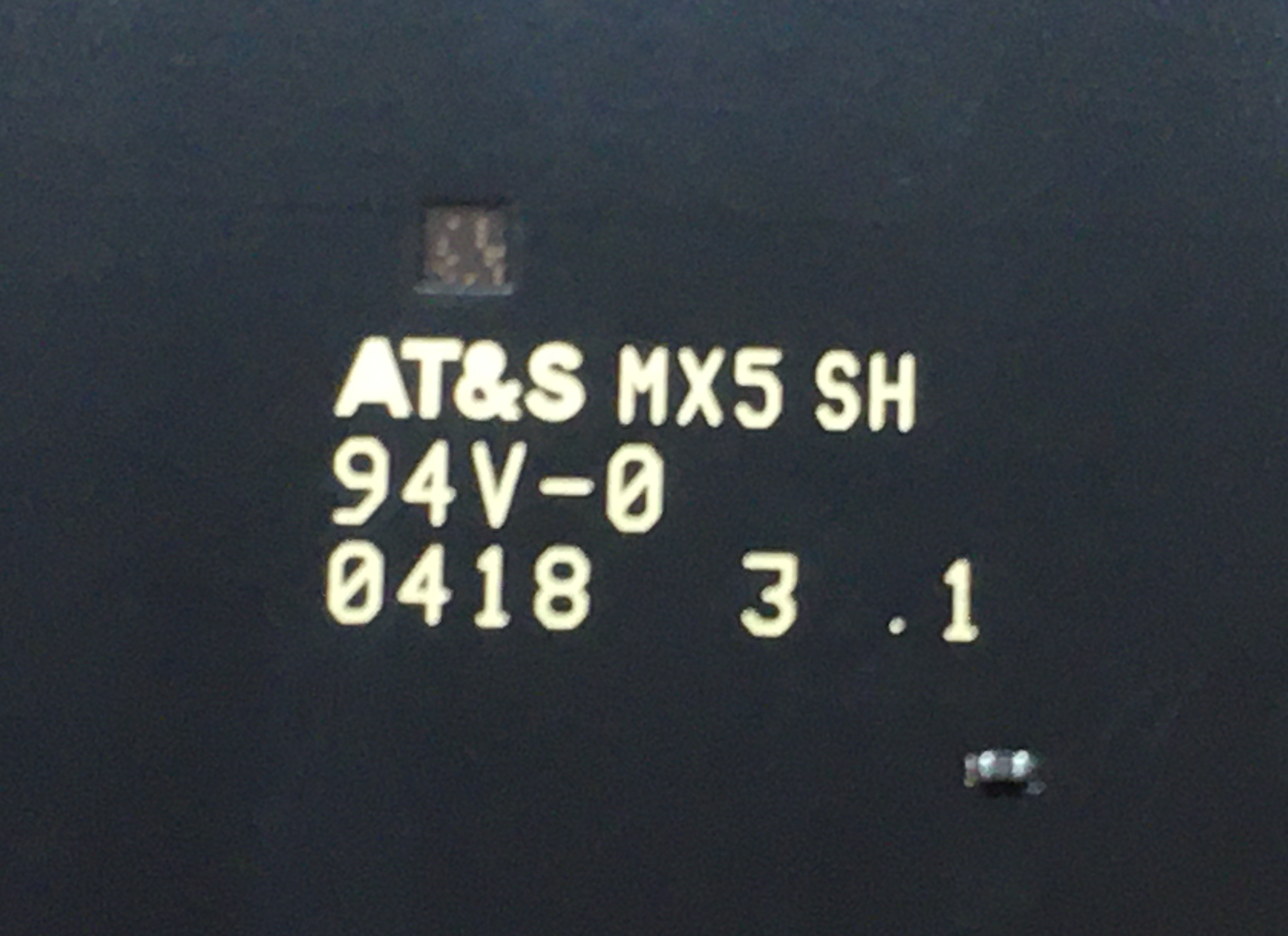
PCB manufacturing marks: AT&S MX5 SH 94V-0
0418 - Fourth week of 2018?
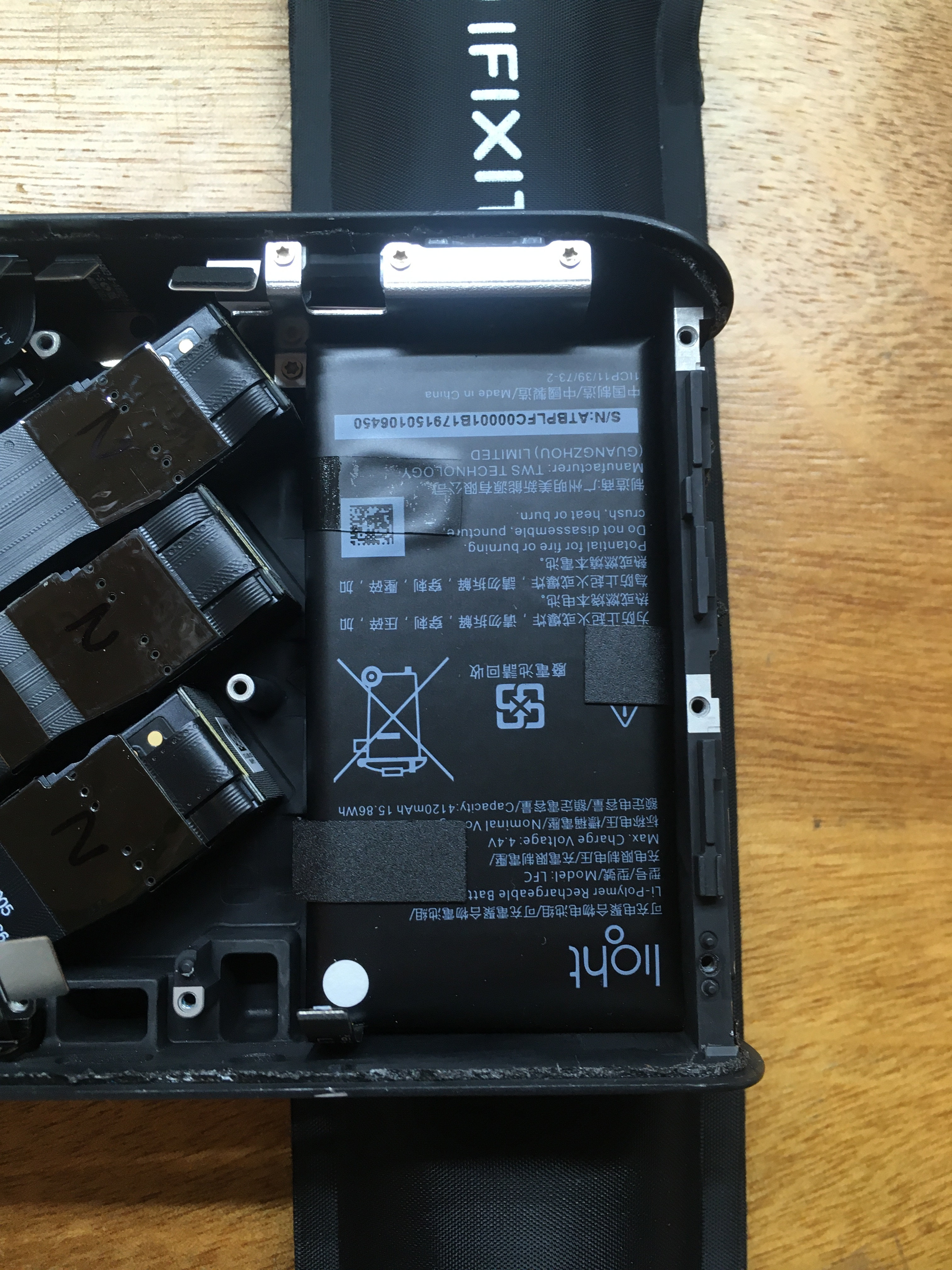
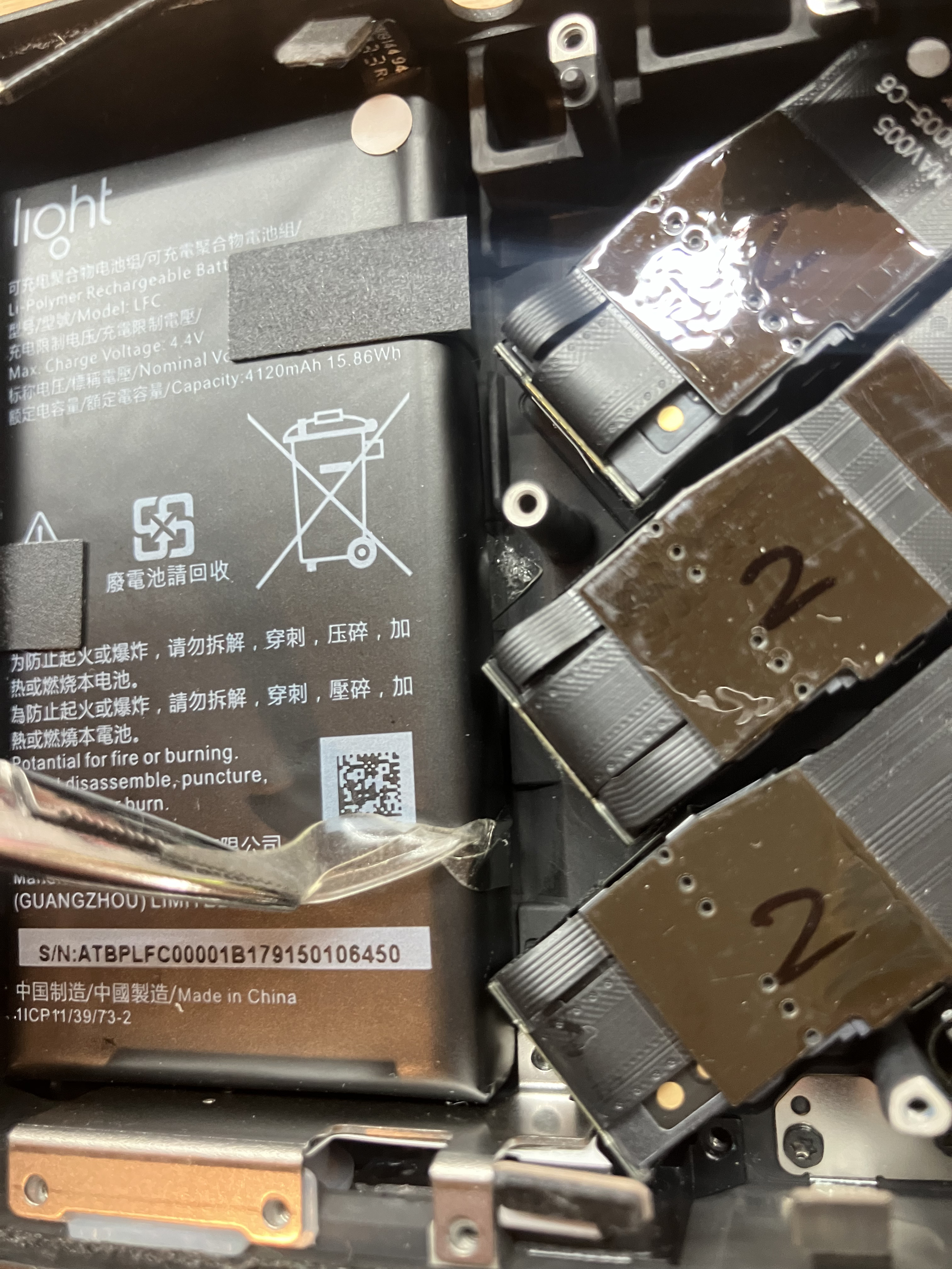
Replacing the battery?
The battery is glued to the aluminum chassis.I've poked at it a bit, but I'm extremely hesitant to do much more than gently tug at it, as it's essentially a small pyrotechnic device. There is no reasonable way to get any kind of a shim in there without removing camera modules. A brave soul might be able to dismantle it in place (i.e. cut open the branded cover and remove cells). At the moment, I'm experimenting with heating up the camera body with the iFixIt "iOpener" heat pack, in the hopes that the adhesive detaches under the pull of gravity. I may switch to a proper heat gun, but again I'd be playing with fire.
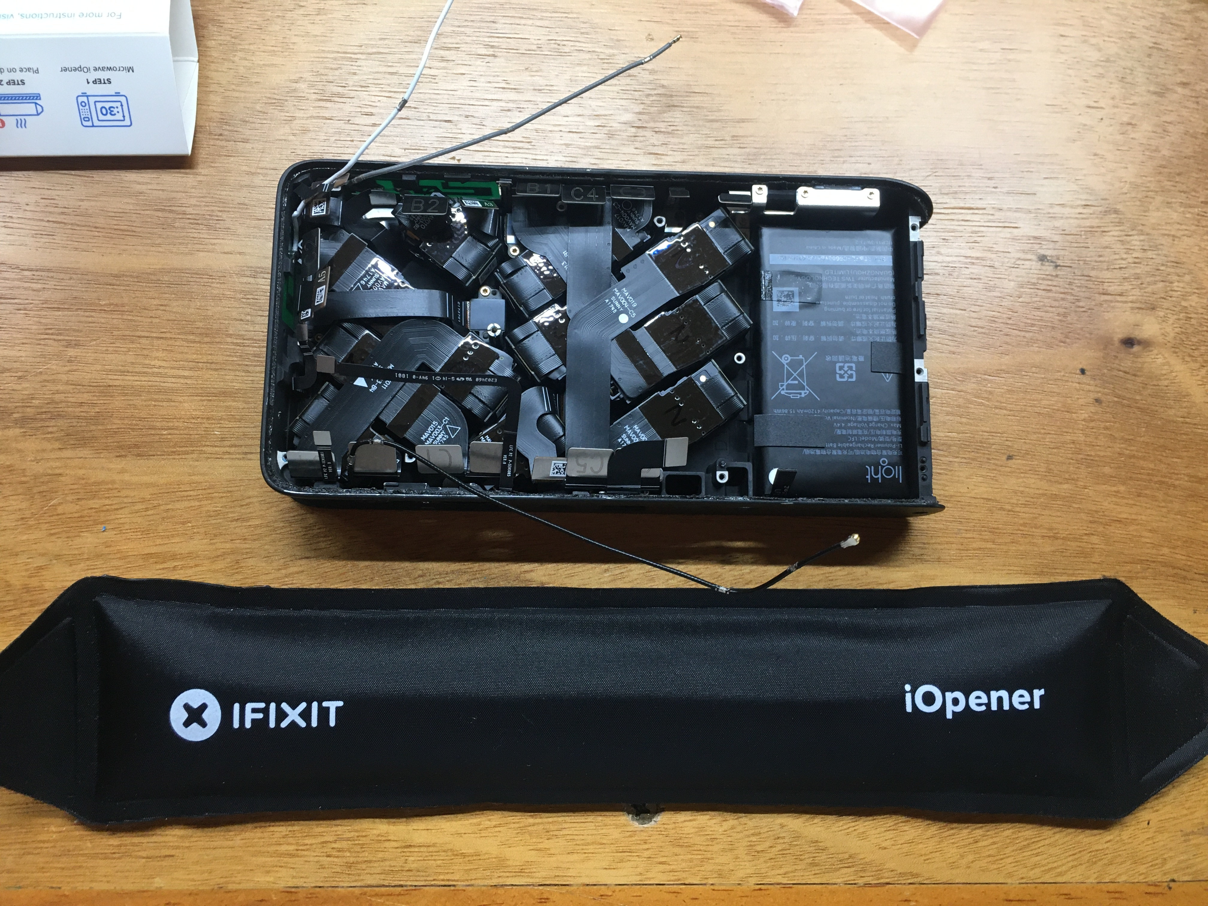
No go. Glued in.
Concluding Thoughts
I'm no physicist, but trying to emulate DSLR quality photos with an array of smaller sensors and some software strikes me as questionable at the outset. Some credence is lent to the idea by cell phone manufacturers embedding multiple cameras in their flagship models, but those systems are designed to excel in the most common use-cases: selfies and simple scene photography. They certainly aren't trying to replace telephoto lenses. There is no replacement for displacement, as the saying goes with cars. In photography, simple physics dictates that there is no replacement for big, contiguous sensors and proper optical paths. All the software in the world can't fill in data that wasn't captured in the first place. However, the most egregious failure of the L16 design is that it was clearly constructed to never be opened; the user can't even replace the battery. I can't think of a single other example of an unreplaceable battery in the camera market. This is an a absurd idea for such an expensive device - except in the cell phone industry, where it is common to drop multiple thousands on personal devices that only last a year or two due to general wear and tear, deliberately sunsetted software support, and/or users desire for the next gadget on the release cycle. Given all the apparent design decisions, I have no doubt the engineers came from that market. I'm really curious what their internal justification was for the no-open design and the glued battery.Was there going to be some kind of service plan, send in the camera and fifty bucks and get the battery replaced? Maybe a swap service, send in the old one for recycling/refurbishment, get a new (or refurbished) one? Were these things they told themselves that they'd get to when they got it out the door? Was the design process so rushed they couldn't do any better? Did they just not give a crap? Did they expect people to just toss a $2000 camera in a couple years when the battery died?
Future Work
I want to remove and dismantle the battery, at least to discover the pin-out of the connector. Speaking of pin-out, mapping out the contact points on the proprietary "Light" connector on the bottom would be very useful and interesting.Its PCB connector is quite close to the battery connector; I wonder if an external battery pack can be attached, solving the worn out battery issue without opening the camera.
(I can't find the page now, but I swear I saw a reference to an external battery pack accessory somewhere...) I should probably pop open those RF cans and take a close look at the chips underneath. No SoC that I am aware of has enough camera ports to handle the 16 image sensors this device has. Did they use FPGAs, MIPI or parallel switches, or roll their own silicon? Inquiring minds want to know!
Battery Teardown (November 11th, 2024)
Finally! This was supposed to happen a lot sooner, but I misplaced the, uh, remains during a house move. Oops! Lets get right into it:
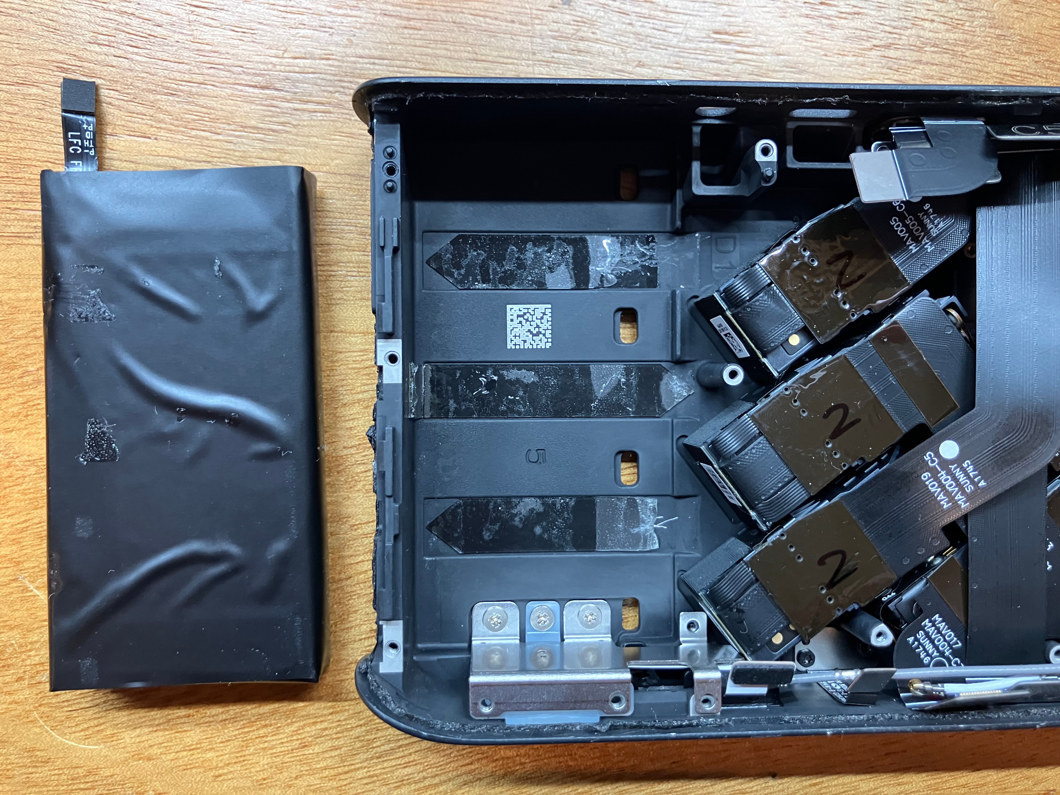
Left, battery in place. Right, glue strip partially extracted.
My first thought was maybe the glue strips come out like they do when replacing a battery in a cell phone - this fits with the overall design paradigm (cellphone engineers building a camera). As suggested last time, I used my desoldering "hot air gun" to heat up the aluminum chassis, on the side opposite of the battery. Not smoking hot - the left-over tape residue on the front didn't even deform or discolor.
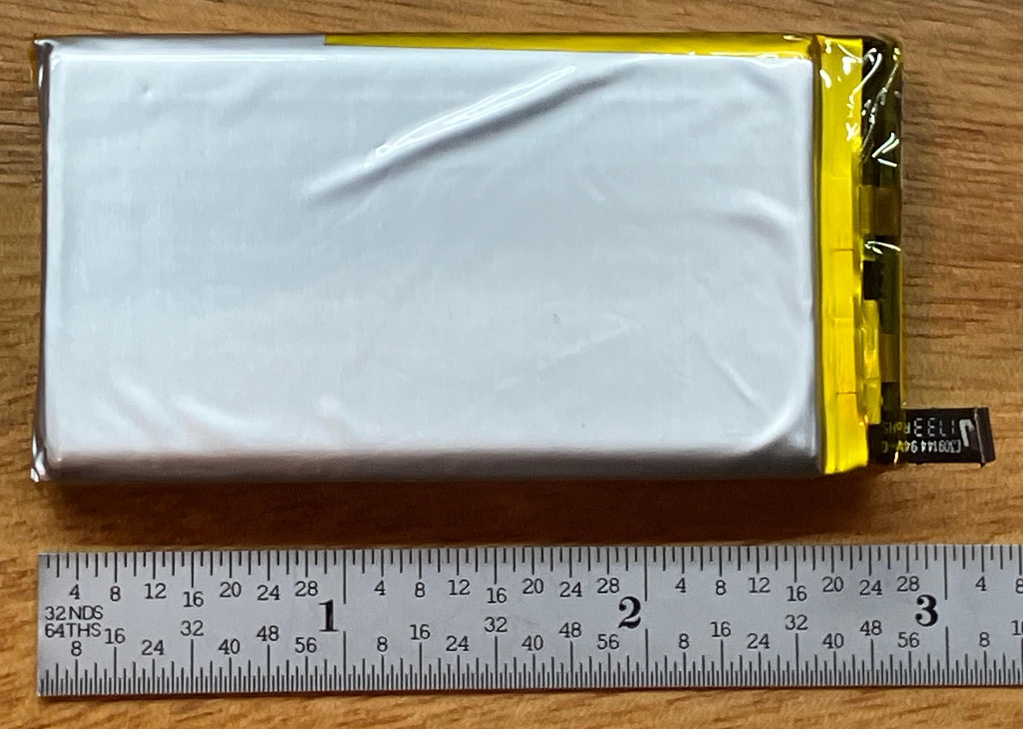
Battery out!
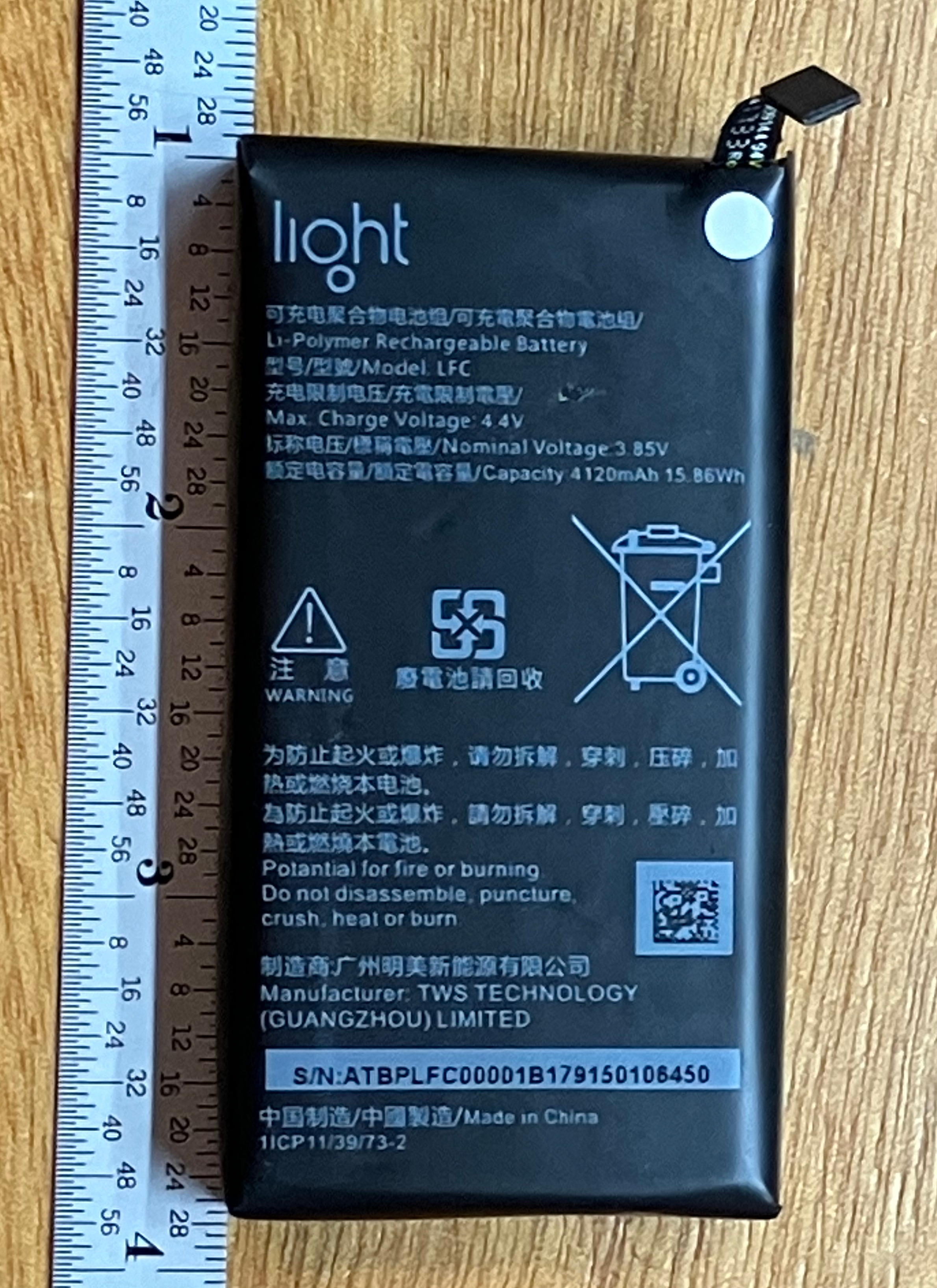
Ruler for scale.
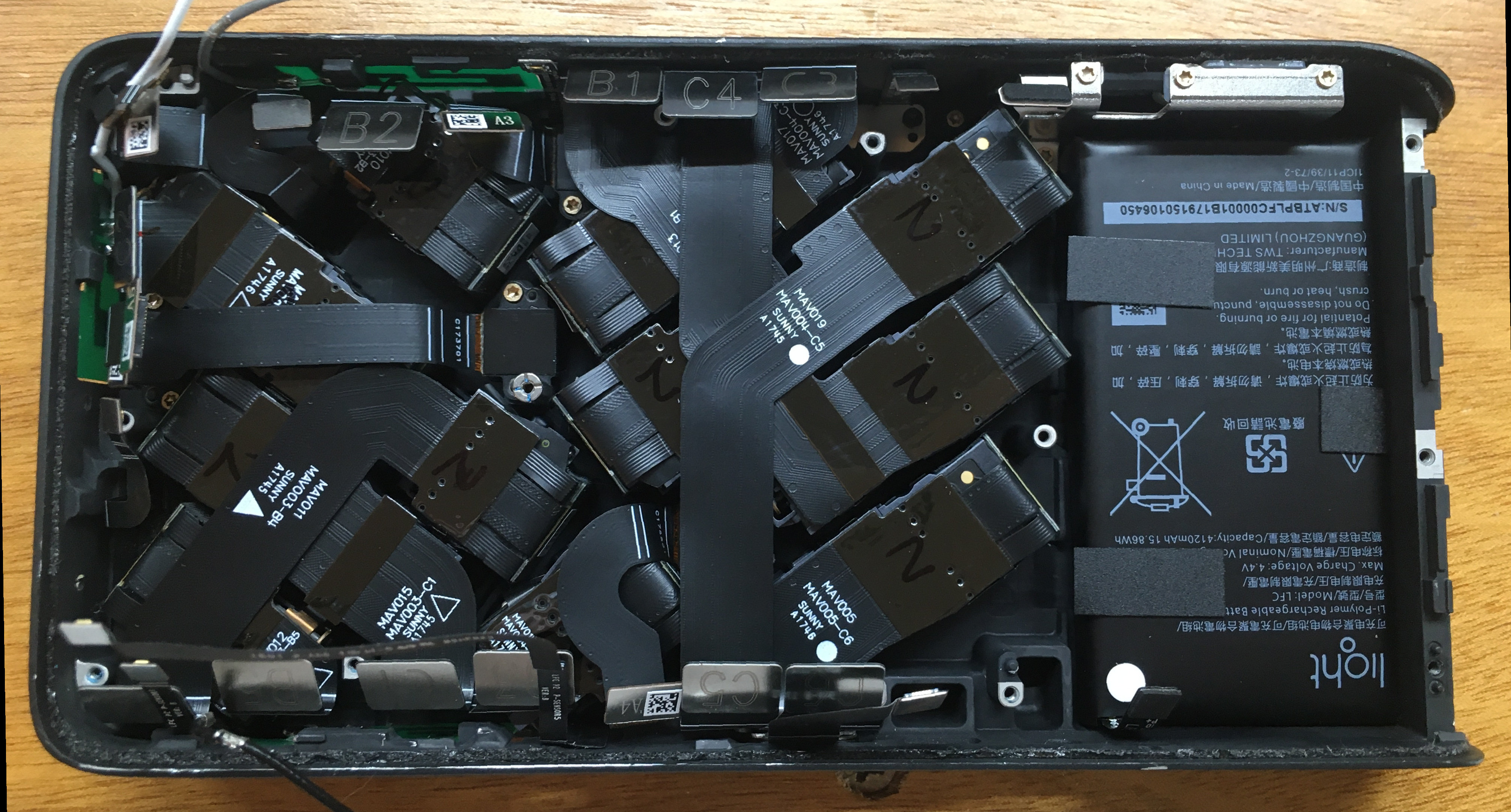
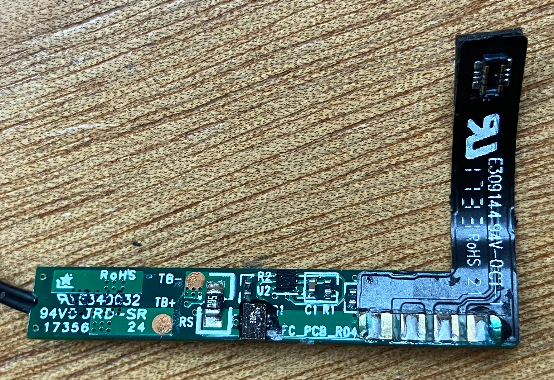
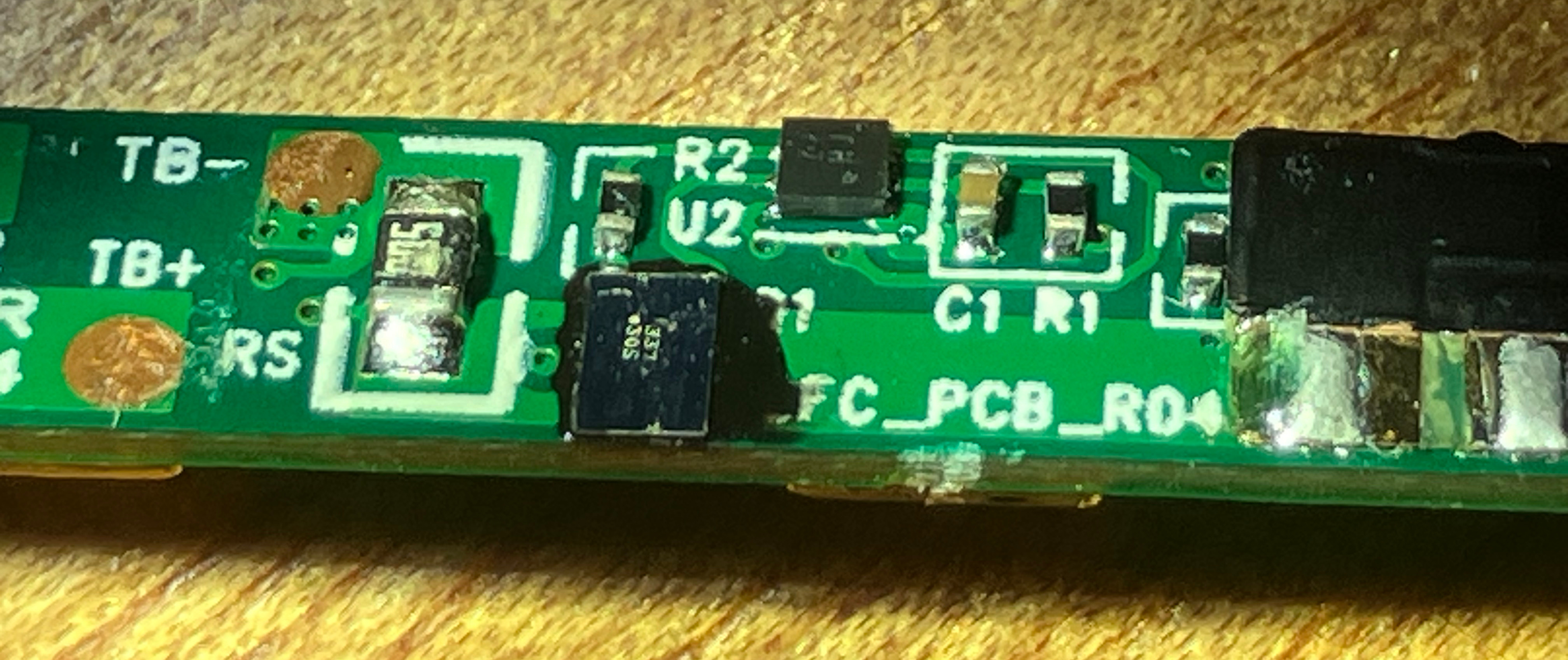
The "max charge voltage" is 4.4 volts (unusual, 4.2 V is much more common), which means it contains typical Lithium polymer cells and not Lithium Iron Phosphate, which "LFC" might otherwise suggest.
Given the voltage and the overall thickness of the battery it's clearly two cells in parallel. Nominal voltage is 3.85 V and capacity is listed as 4120 mAh, or 15.86 Wh. Nothing fancy here.
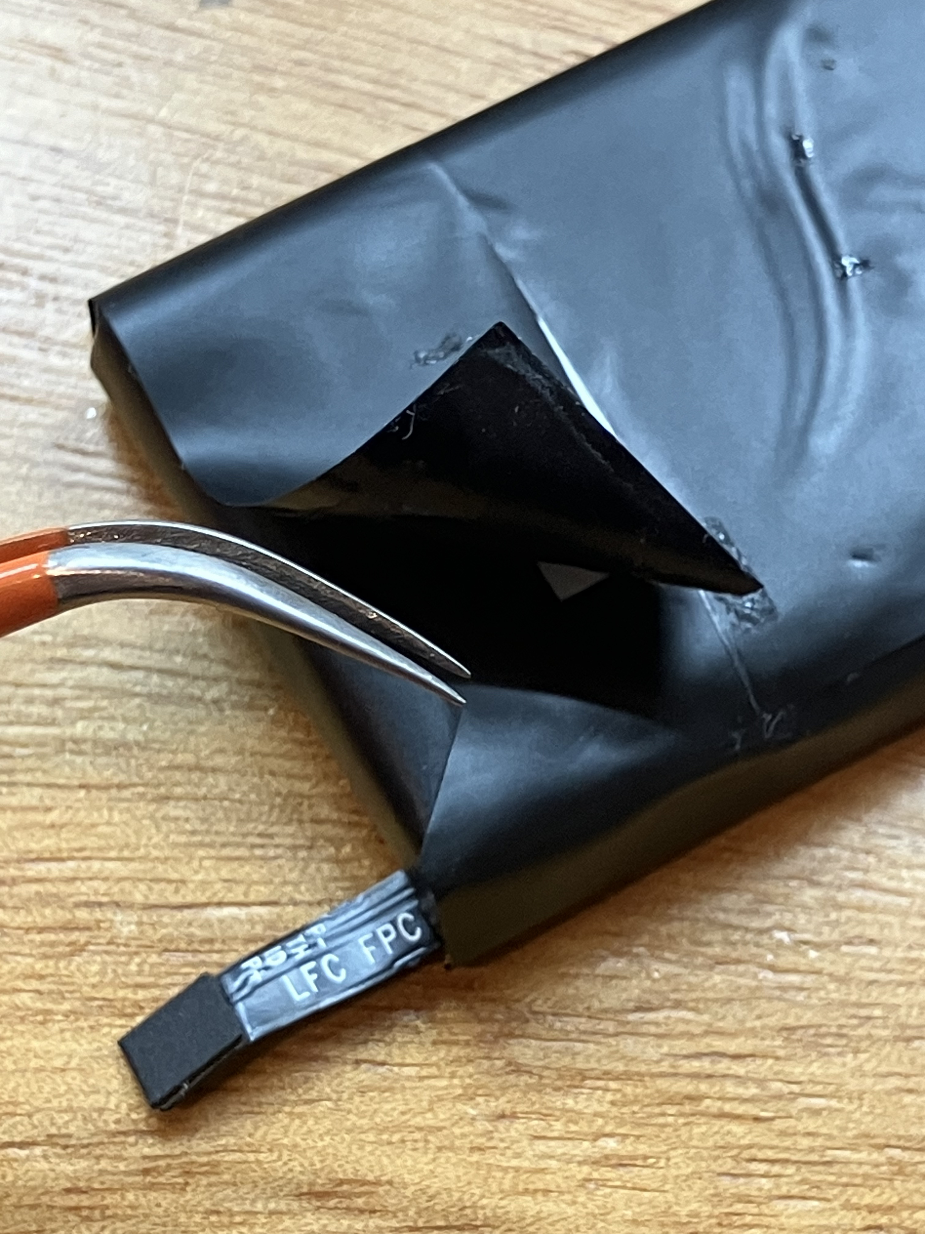
Rrrrriiiipppp
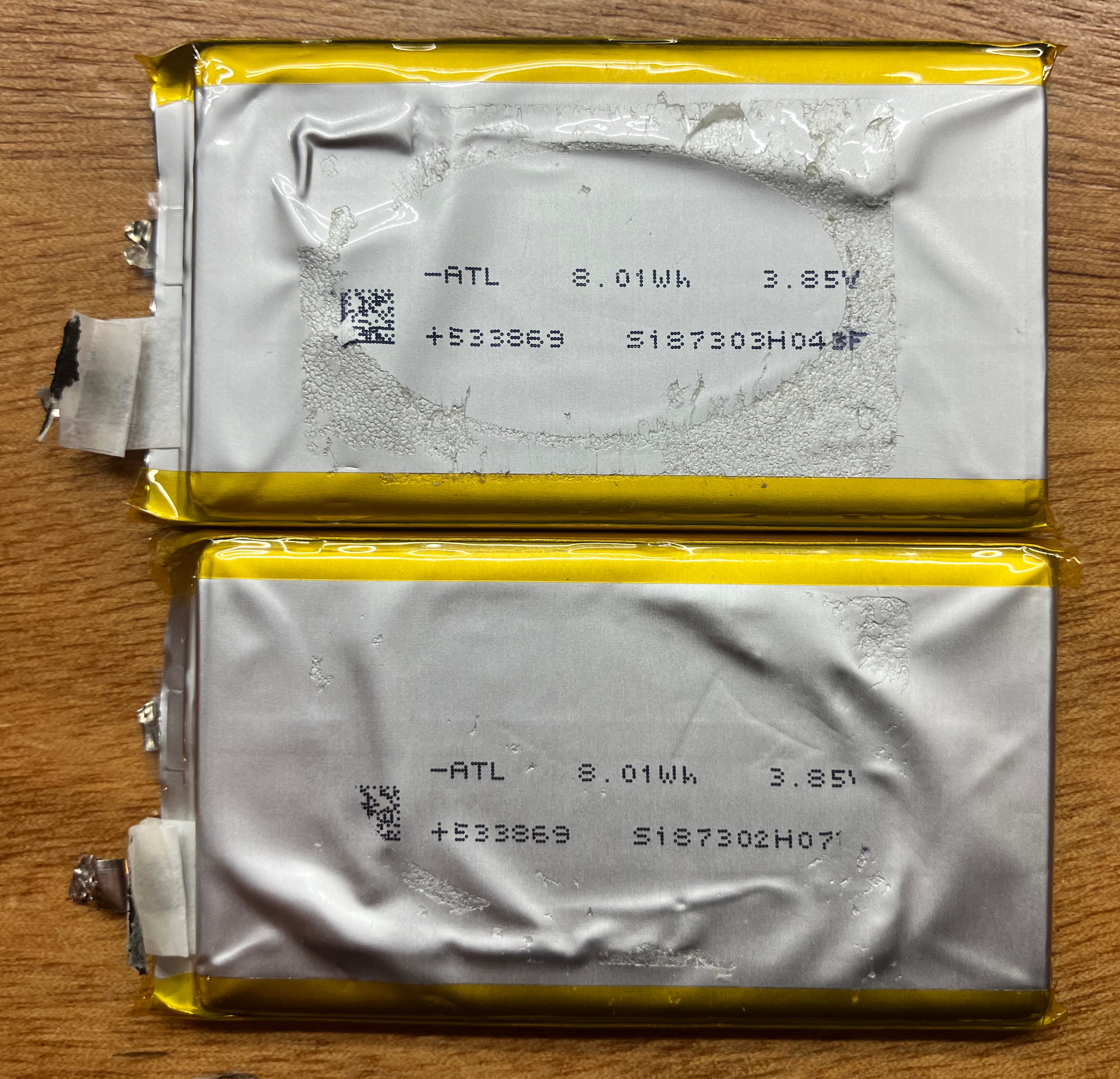
I was pretty sure this battery had two cells in parallel, but this is positive confirmation of such.
If you are looking to rebuild the battery, you should be able to connect a cell to either pair with no issues.
Clearly this isn't a radio, so why was it used here? Heat dissipation?
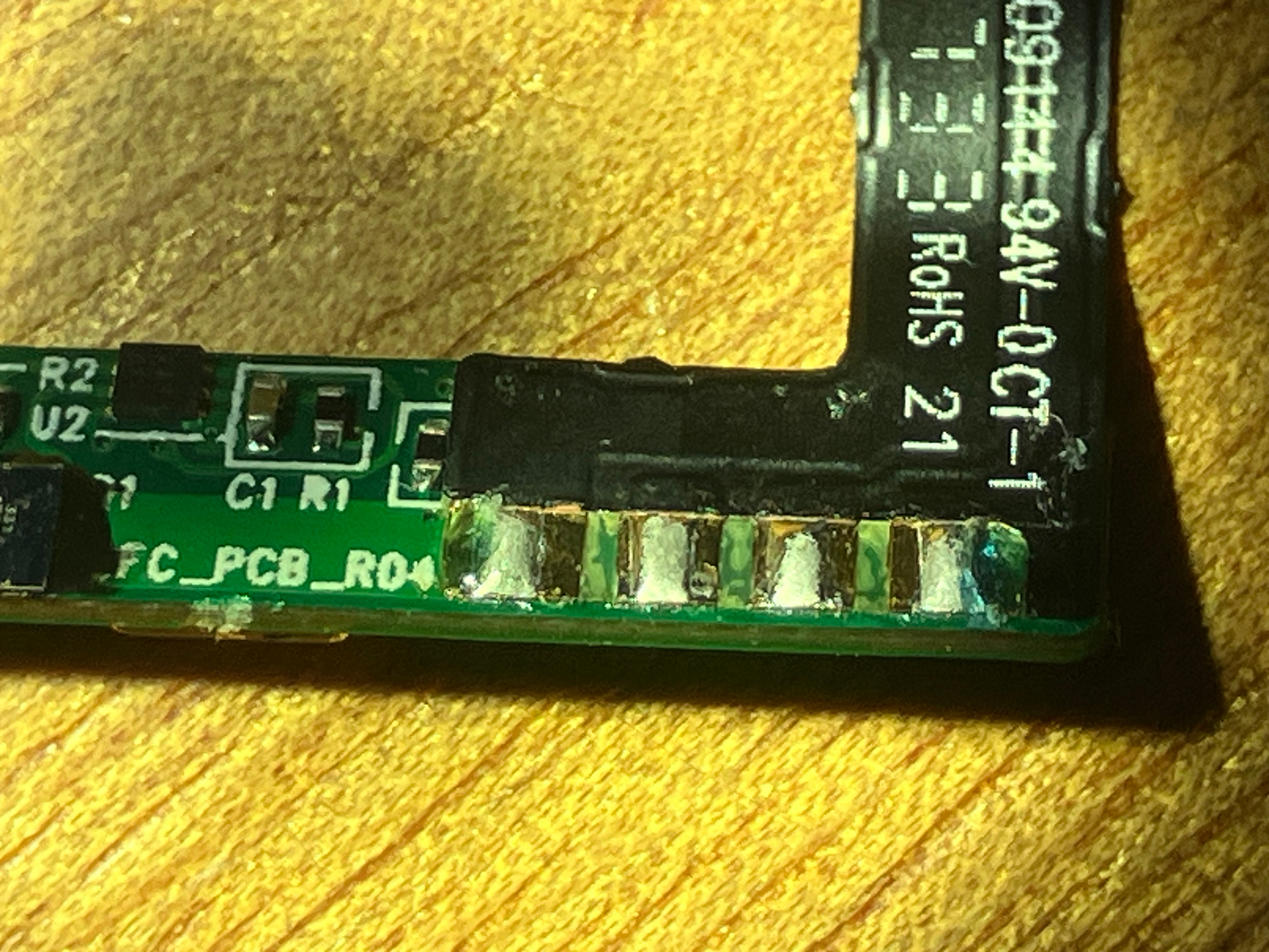
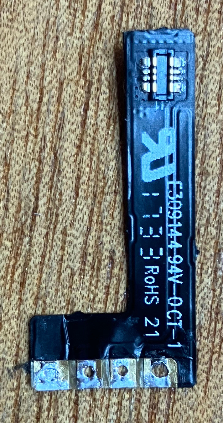
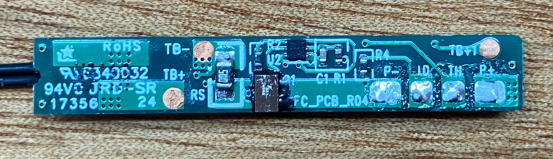
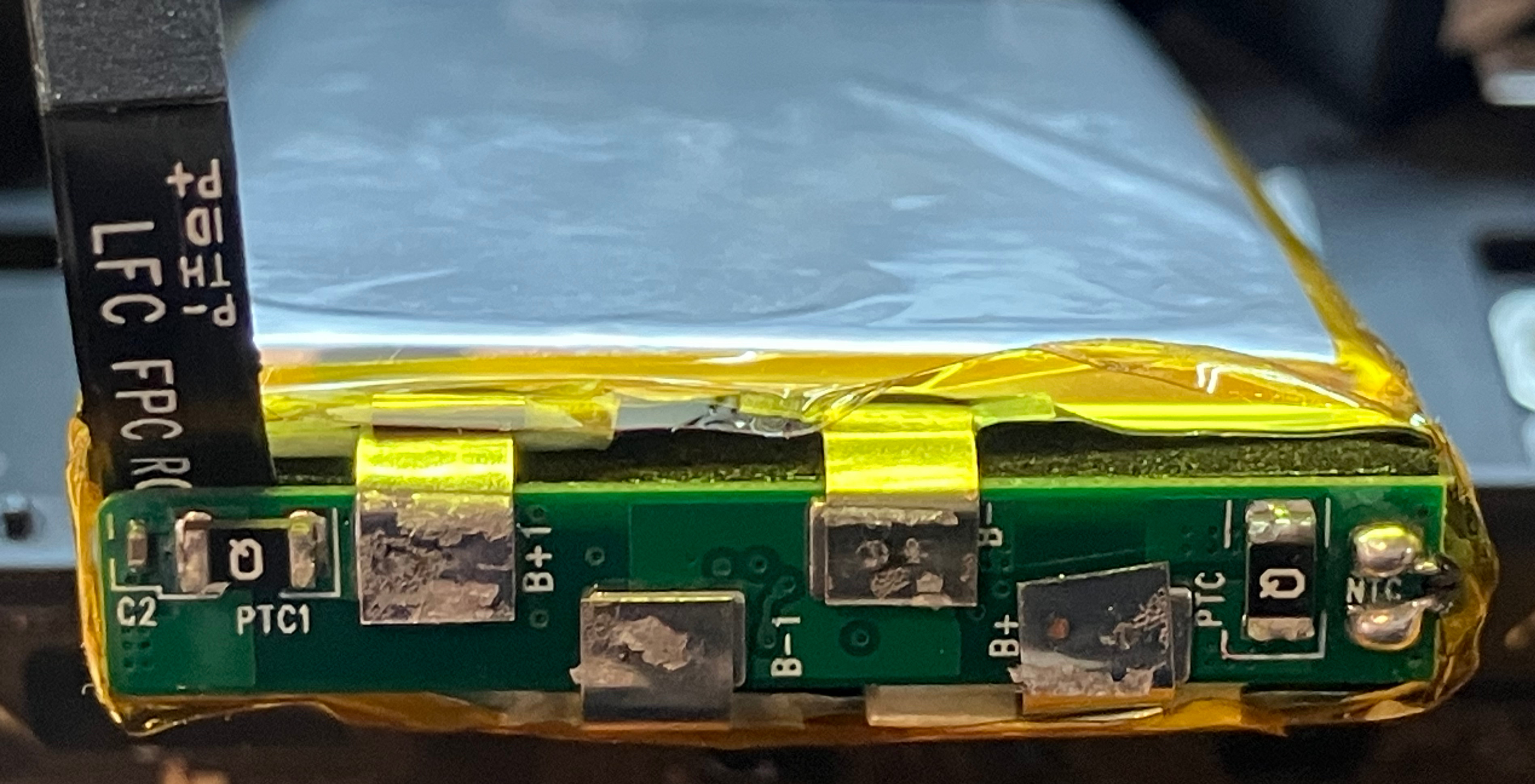
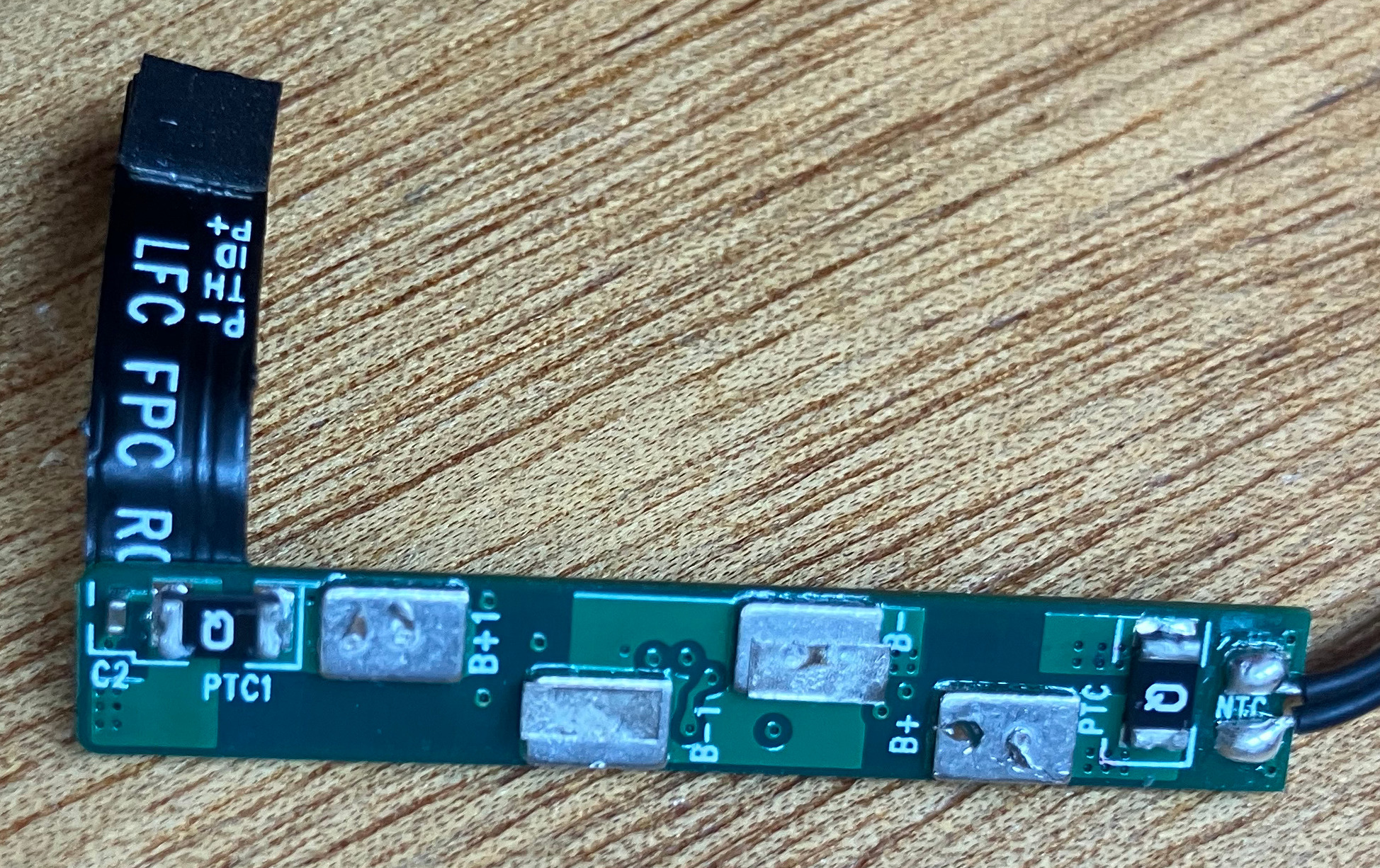
Clearly it was important enough to "spend" and entire pin on. Curious. The sharp-eyed among you have likely noticed they hinted at this already - check out the back of the flex cable a couple of images up. They list out "P-/TH/ID/P+". Unfortunately they don't make mention of exactly which pin is what - would have really saved us all this trouble. Oh well.
And now the moment you have all been waiting for: What the hell is the pinout?! Here you go:
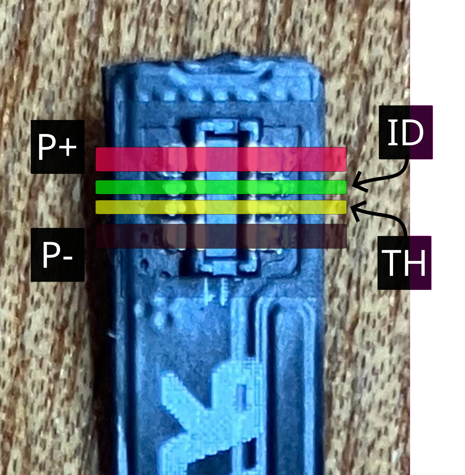
I strongly suspect there was a planned "external battery" accessory, which might bypass the "dead battery" lockout issue that I'm having.