
Teardown of the Kodak Theatre HD Player (L153)
Last Update: June 14, 2020
Look what I found! I was browsing the shelves at a local surplus dealer and I saw this thing sitting on top of a pile of network switches. It had a decent amount of heft and was only five bucks so I picked it up (along with a box full of backup tapes, not joking) figuring it might have a nice little ARM board inside, or at the very least would be interesting to take apart. (Apologies for the low quality photos. All I had was my little point-and-shoot from 2007.)- Hardware and Mechanical
- UART serial port
- Networking
- Capturing the Firmware
- Dismantling the Firmware
- Bricked! (Plus some JTAG work)
- Further Resources
Hardware and Mechanical
This is what the label on the bottom looks like: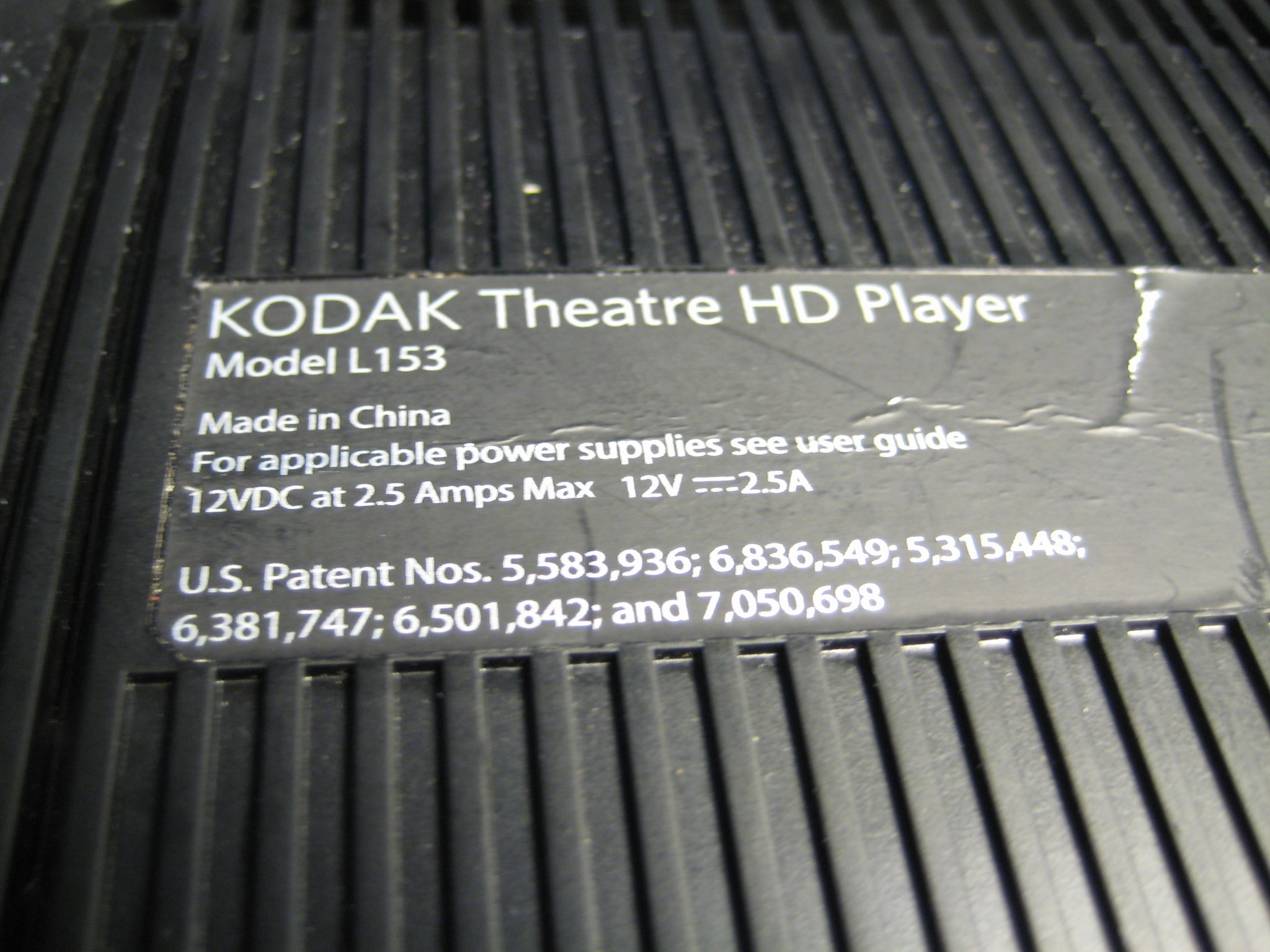 The case screws are hidden under the back two rubber feet (the ones closest to the side with all the ports):
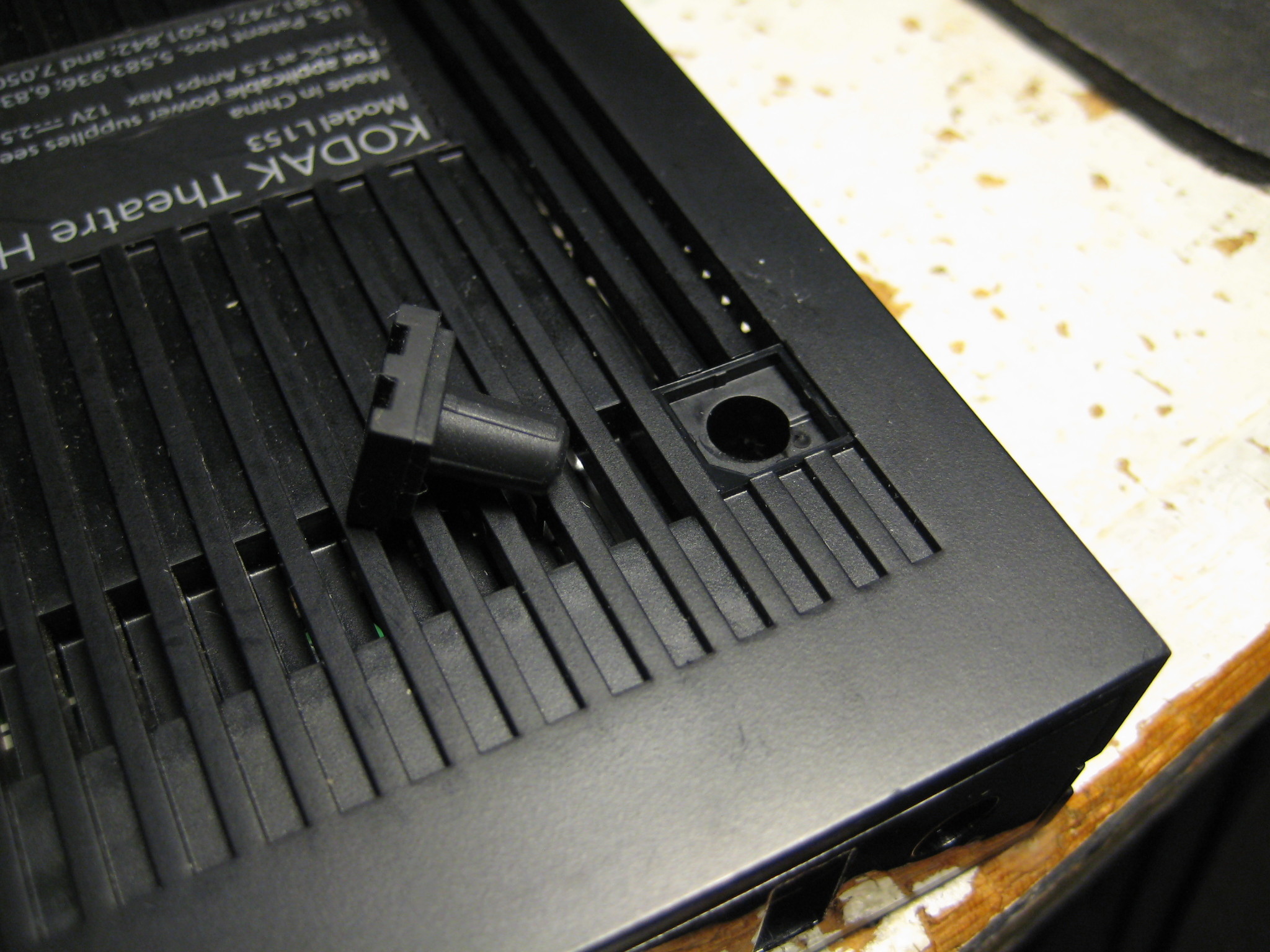 There are a bunch of plastic tabs around the perimeter but a little persuasion and a shim were at that were needed to pull the bottom off. In these photos, the front of the unit is pointing toward the bottom of the photo.
Note the aluminum foil tape. The metal cover is also glued to the bottom shield along the back ports - be prepared to get creative with a knife or similar.
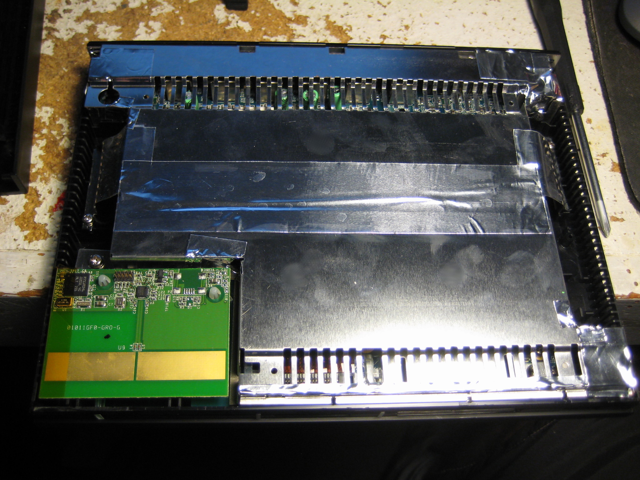
Also be aware that little notched tabs are used to hold the two halves of the metal shield together, not unlike how the plastic cover was held in place.
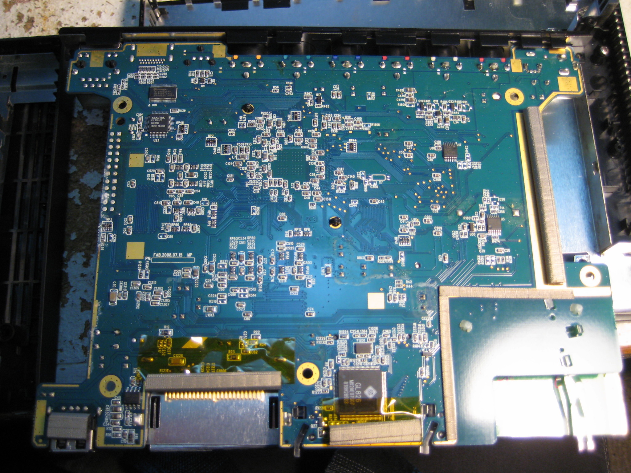
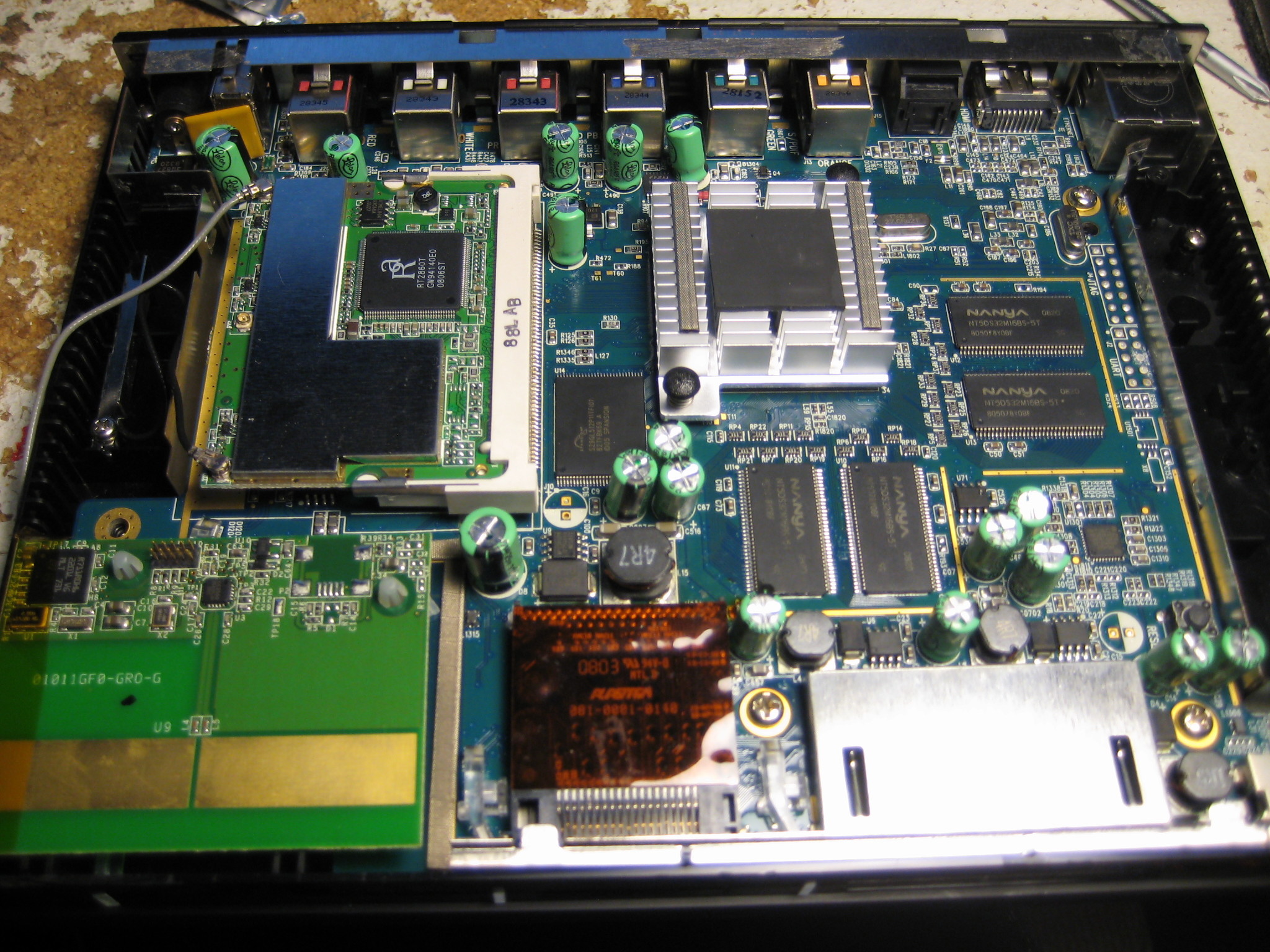 Wow! Look at all that! Seems like a pretty straight forward SBC - I see the front card slots and back ports, RAM, flash, a wifi card in a mini-PCI slot, some power stuff in the upper left corner, something unusual in the bottom left, and a pile of support parts. There is even a reset button (lower right, above the caps)!
Let's take a look at that thingy with the big PCB trace antenna on the bottom left:
Wow! Look at all that! Seems like a pretty straight forward SBC - I see the front card slots and back ports, RAM, flash, a wifi card in a mini-PCI slot, some power stuff in the upper left corner, something unusual in the bottom left, and a pile of support parts. There is even a reset button (lower right, above the caps)!
Let's take a look at that thingy with the big PCB trace antenna on the bottom left: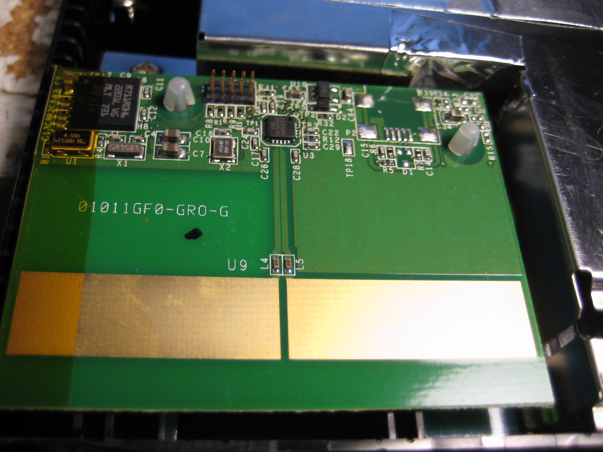
 My best guess is that this is the remote control transceiver. I didn't find the remote control for this thing when I was in the surplus shop so I don't know for sure, but I didn't notice an IR receiver of any type on the main board so I think this is a pretty good guess.
It's actually a module which can be unplugged from the main board. I failed to take any photos but there is a six (I think?) pin connector on the back that has the following labels: 3.3V, GND, D-, D+, and a few extra if memory serves.
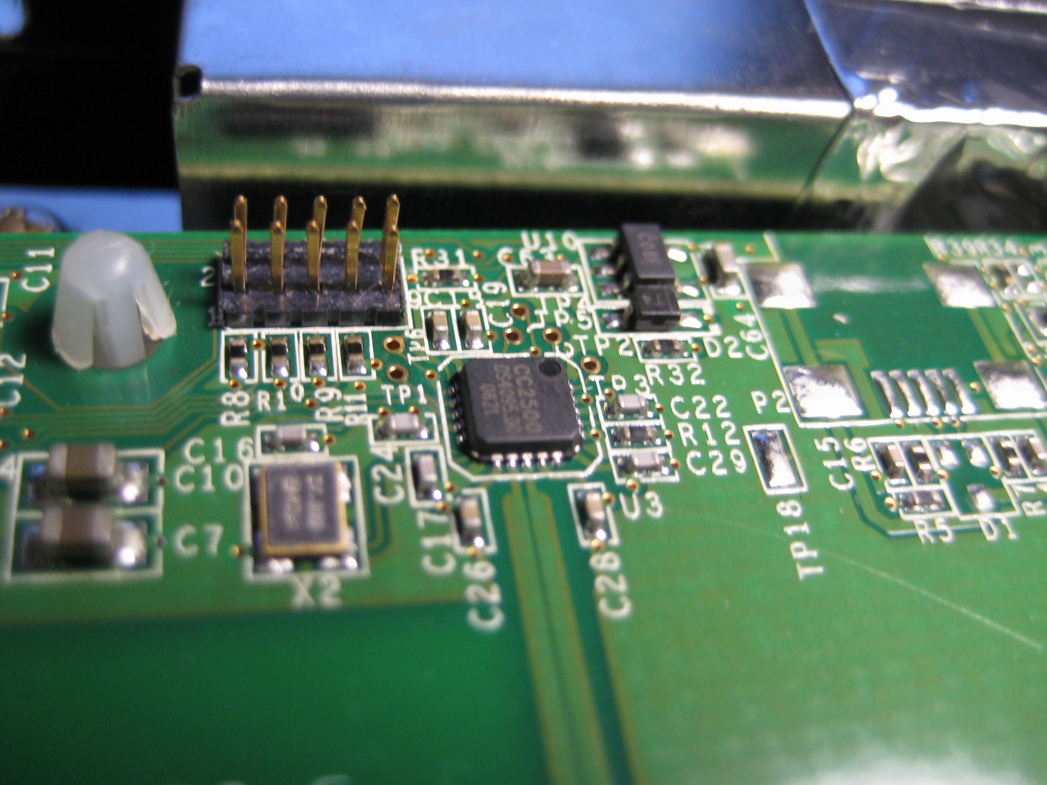
There is an unused USB (miniB?) connector footprint on the board, and a ten pin header which I assume is for programming/debugging.
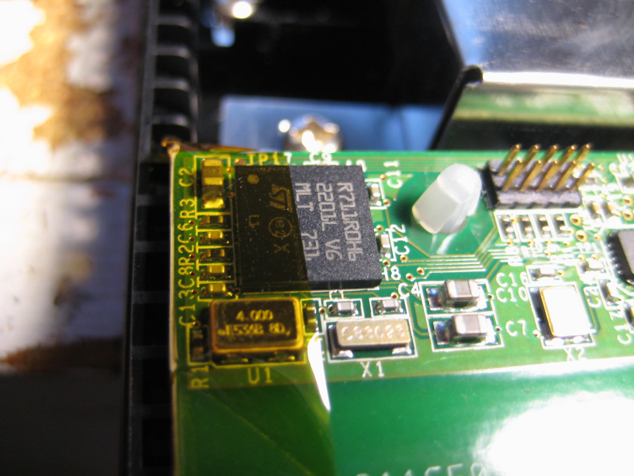
The radio chip itself is a TI CC2500, a "low cost, low power" 2.4 GHz RF transceiver and looks to be what I would consider a good option for building a compact, battery powered remote control system. It only has an SPI interface however, I assume the other chip on the board handles the USB stuff. That chip has the ST logo on it, and is marked as follows:
R711R0H6
2201L V6
MLT 731
A cursory search on the innernettubes doesn't bring up anything, and the number is odd enough that I would assume it to be some custom ASIC. Undoubtedly a microcontroller of some kind but I don't have any information beyond that. [Update 2020-06-14] A sharp-eyed reader has determined that this part is a STMicroelectronics STR71x series ARM7TDMI microcontroller, a forefather of STM32 series. The datasheet is available for the R711R1H6 part, which is very similar to the part listed above. Thanks! The other major parts are fairly normal:
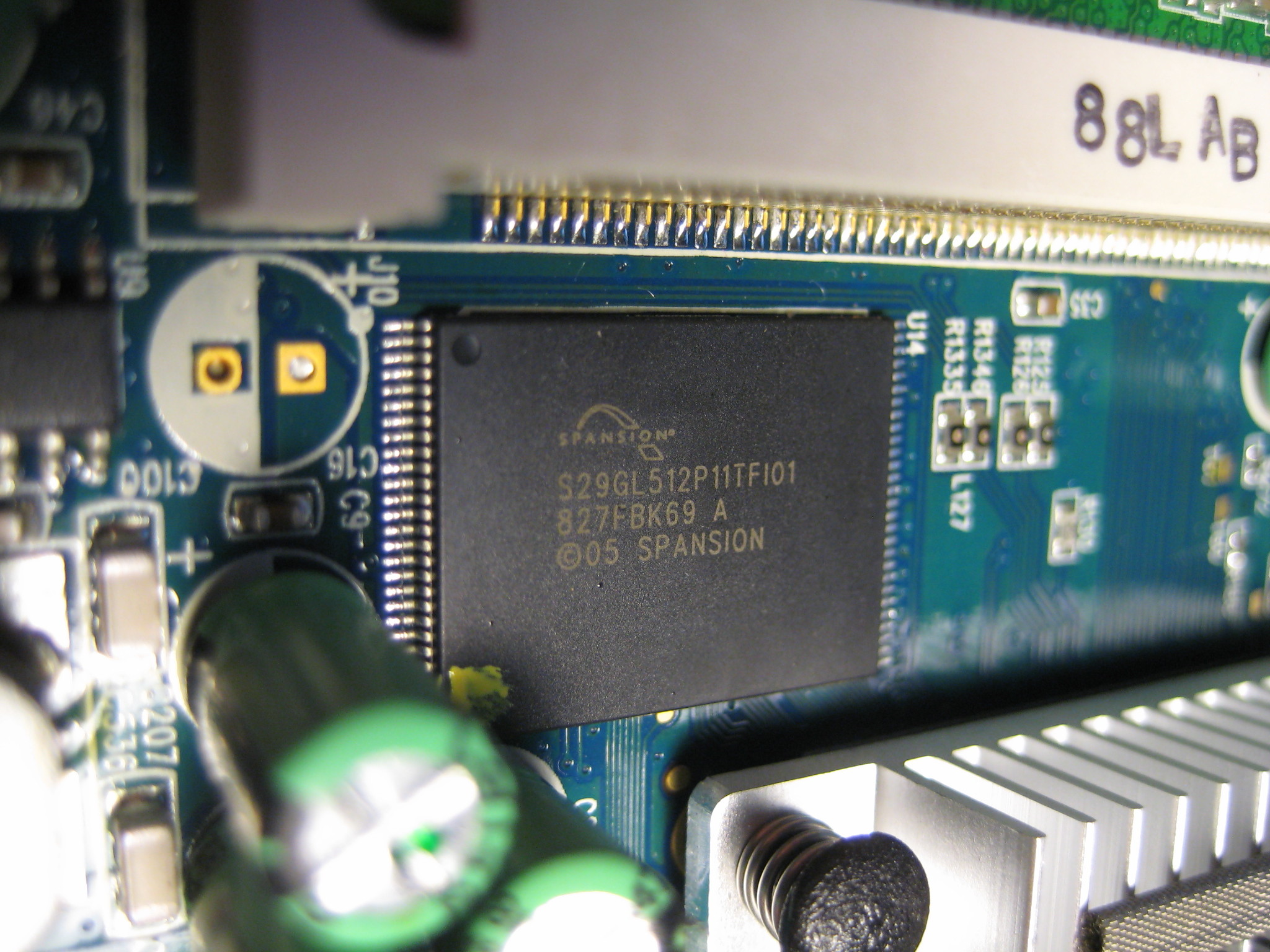
 A Spansion S29GL512P11 flash chip gives this box a 64 MB (512 Mbit) non-volatile memory in a TSOP-56 package. (The only info I can find on it is in here, which appears to be a product guide and not a datasheet.)
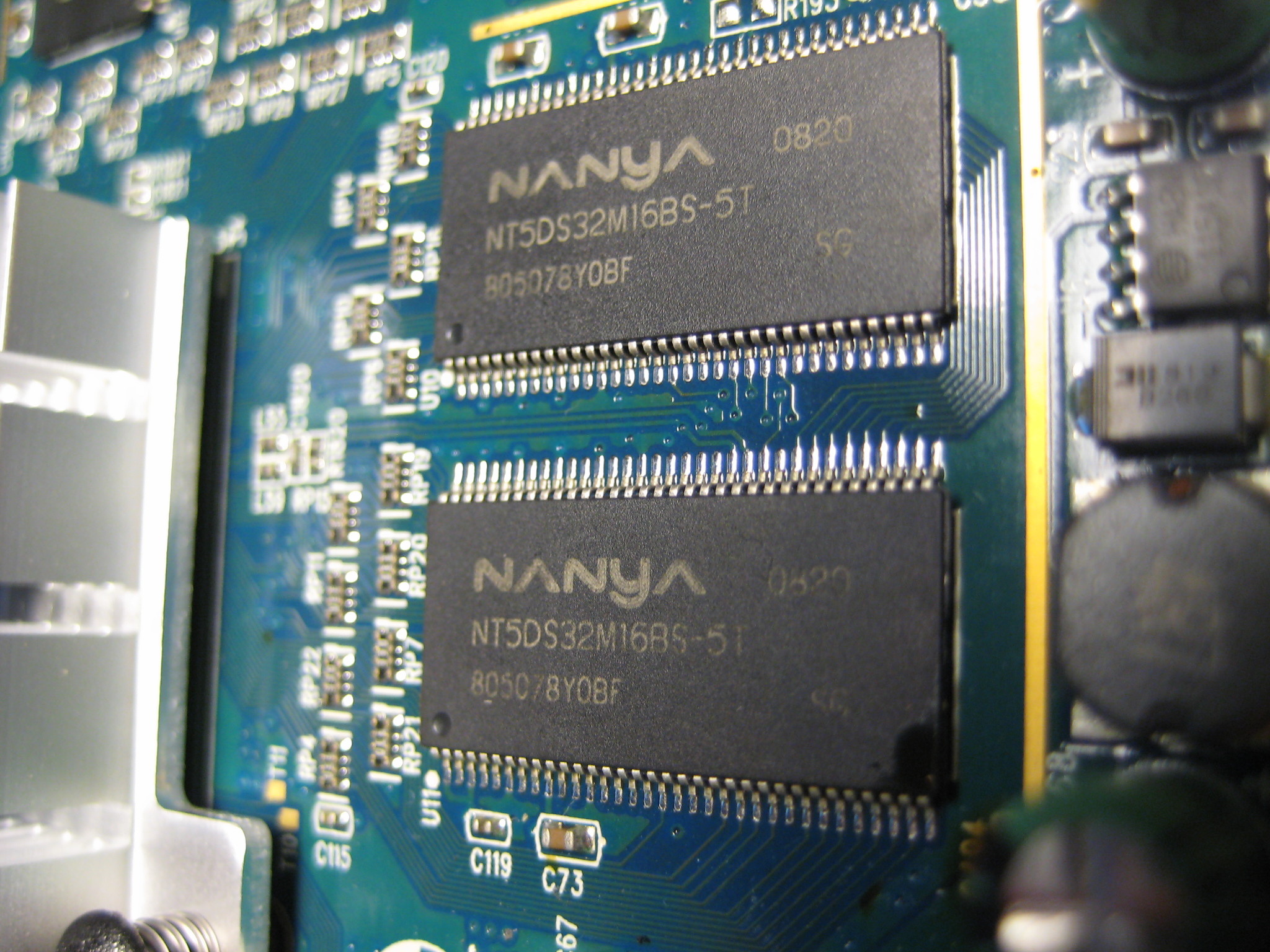
Four Nanya NT5DS32M16BS-5T chips in the 66 pin TSOP-II package provide the RAM. The '-5T' indicates DDR400, the 'S' in the '...16BS' segment indicates it is a 'green' package, and each chip provides 64 MB (512 Mbits) of RAM for a total memory size of 256 MB. Not bad. The datasheet can be found here.
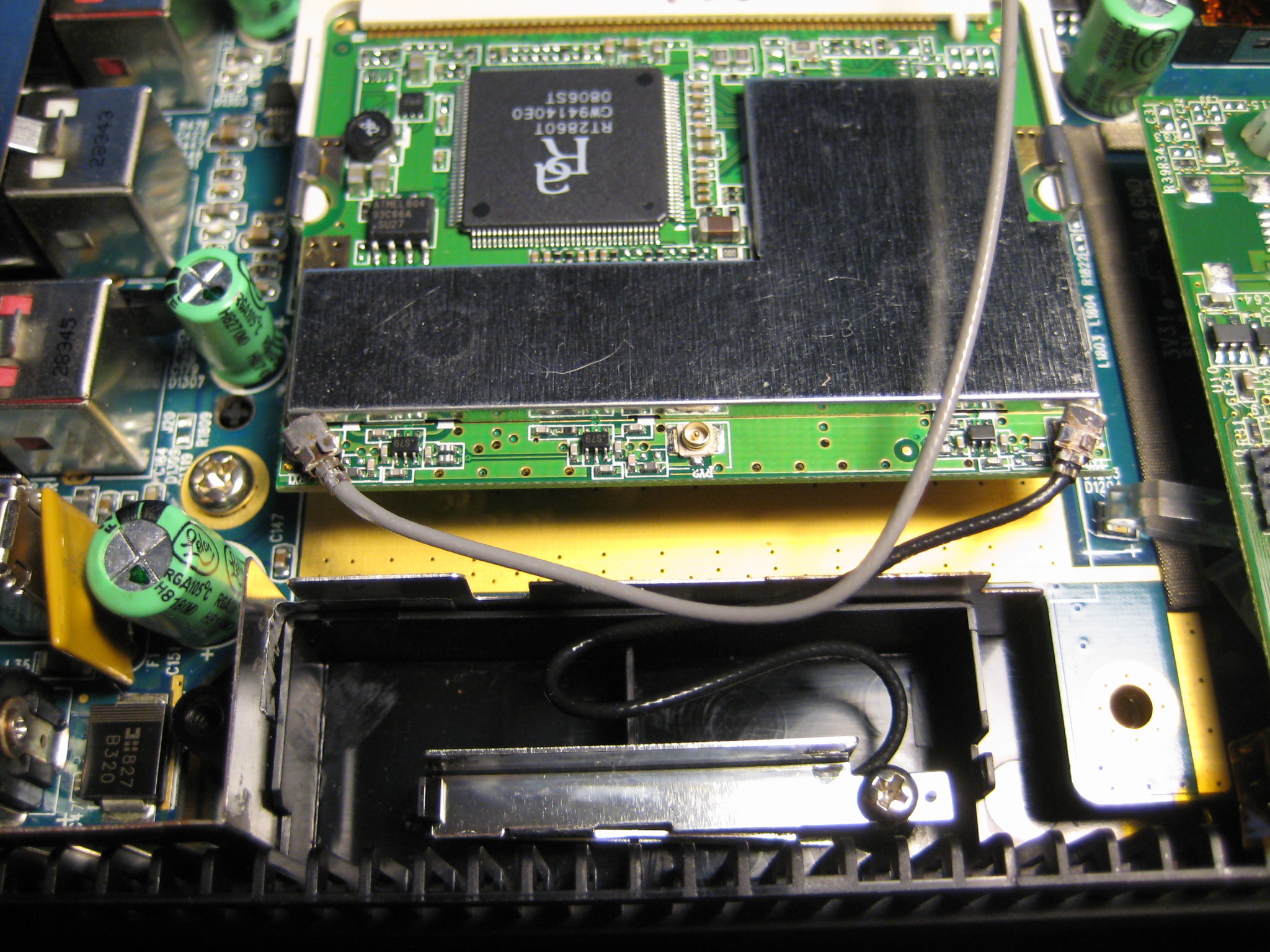
The wifi card is pretty standard. It appears to be a generic device based on the Ralink RT2860T chipset. (I didn't get a photo, but there appears to be a footprint for a "coin" cell holder under the mini-PCI slot. RTC clock backup maybe?)
It's worth pointing out that you can see part of the power supply in the last picture. In particular one can see the large orange rectangle which looks like a polyfuse to me. That's a nice touch; most consumer devices don't bother with extravagances like self-resetting fuses.
A Spansion S29GL512P11 flash chip gives this box a 64 MB (512 Mbit) non-volatile memory in a TSOP-56 package. (The only info I can find on it is in here, which appears to be a product guide and not a datasheet.)
Four Nanya NT5DS32M16BS-5T chips in the 66 pin TSOP-II package provide the RAM. The '-5T' indicates DDR400, the 'S' in the '...16BS' segment indicates it is a 'green' package, and each chip provides 64 MB (512 Mbits) of RAM for a total memory size of 256 MB. Not bad. The datasheet can be found here.
The wifi card is pretty standard. It appears to be a generic device based on the Ralink RT2860T chipset. (I didn't get a photo, but there appears to be a footprint for a "coin" cell holder under the mini-PCI slot. RTC clock backup maybe?)
It's worth pointing out that you can see part of the power supply in the last picture. In particular one can see the large orange rectangle which looks like a polyfuse to me. That's a nice touch; most consumer devices don't bother with extravagances like self-resetting fuses.
y halo thar:
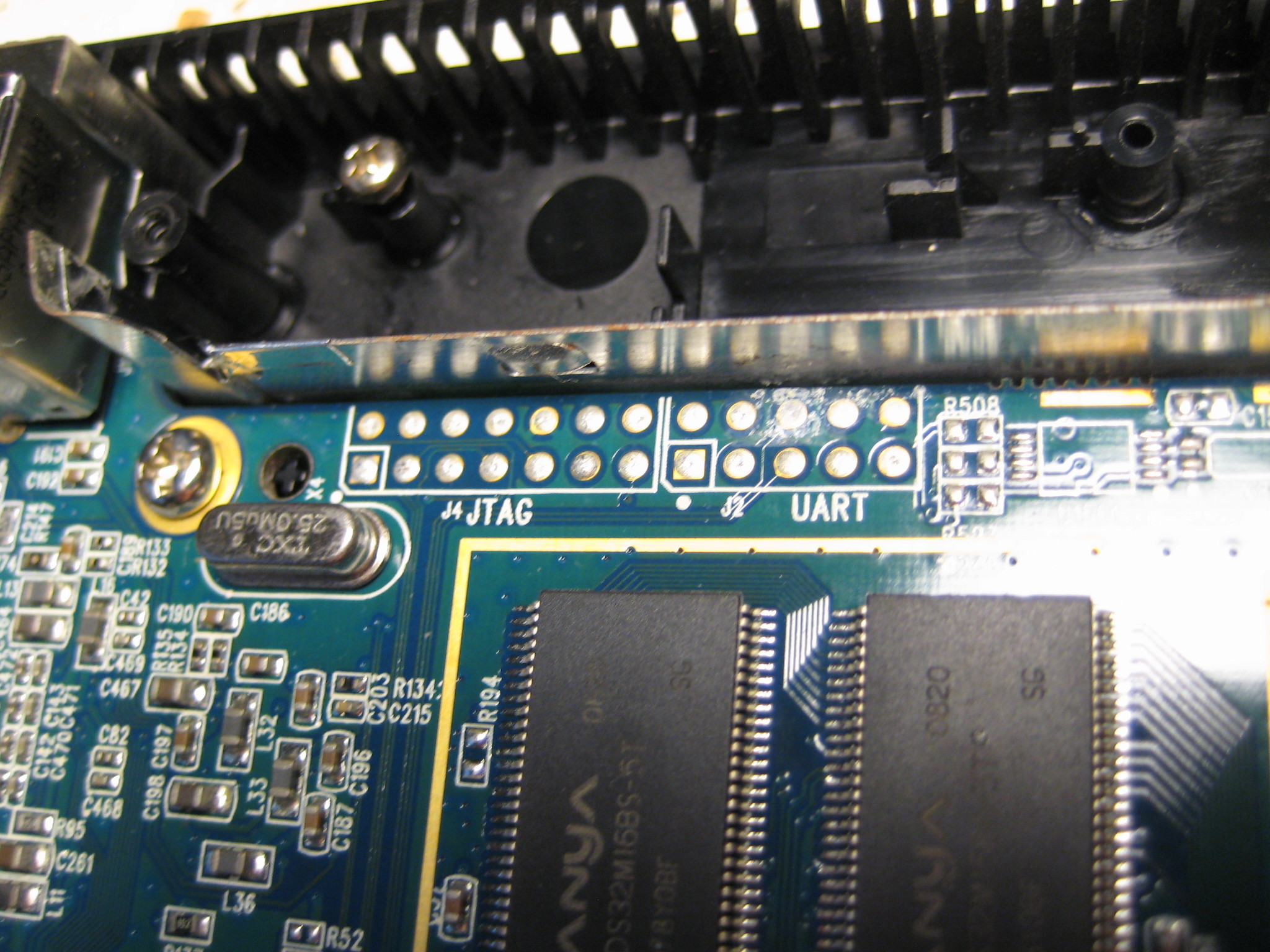 That's nice of them. Kodak engineers (or contractors or whoever) not only provided footprints for both JTAG and UART but also clearly labeled them. Sweet!
Let's take the board out and flip it over. Four screws and fwoop:
 Not much to see here, sadly.
(The board has been flipped right-to-left; the front of the device is still in the bottom of the photo.)
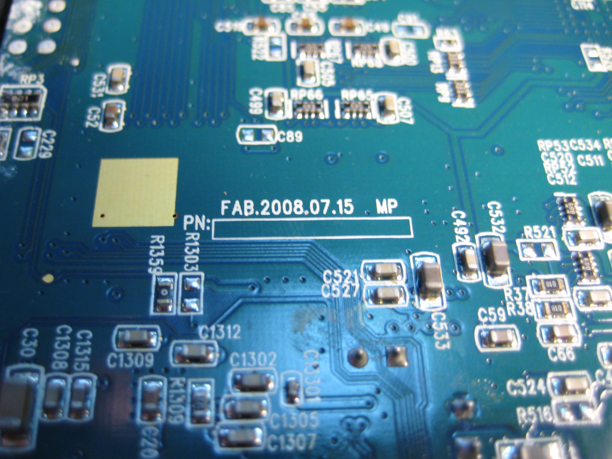
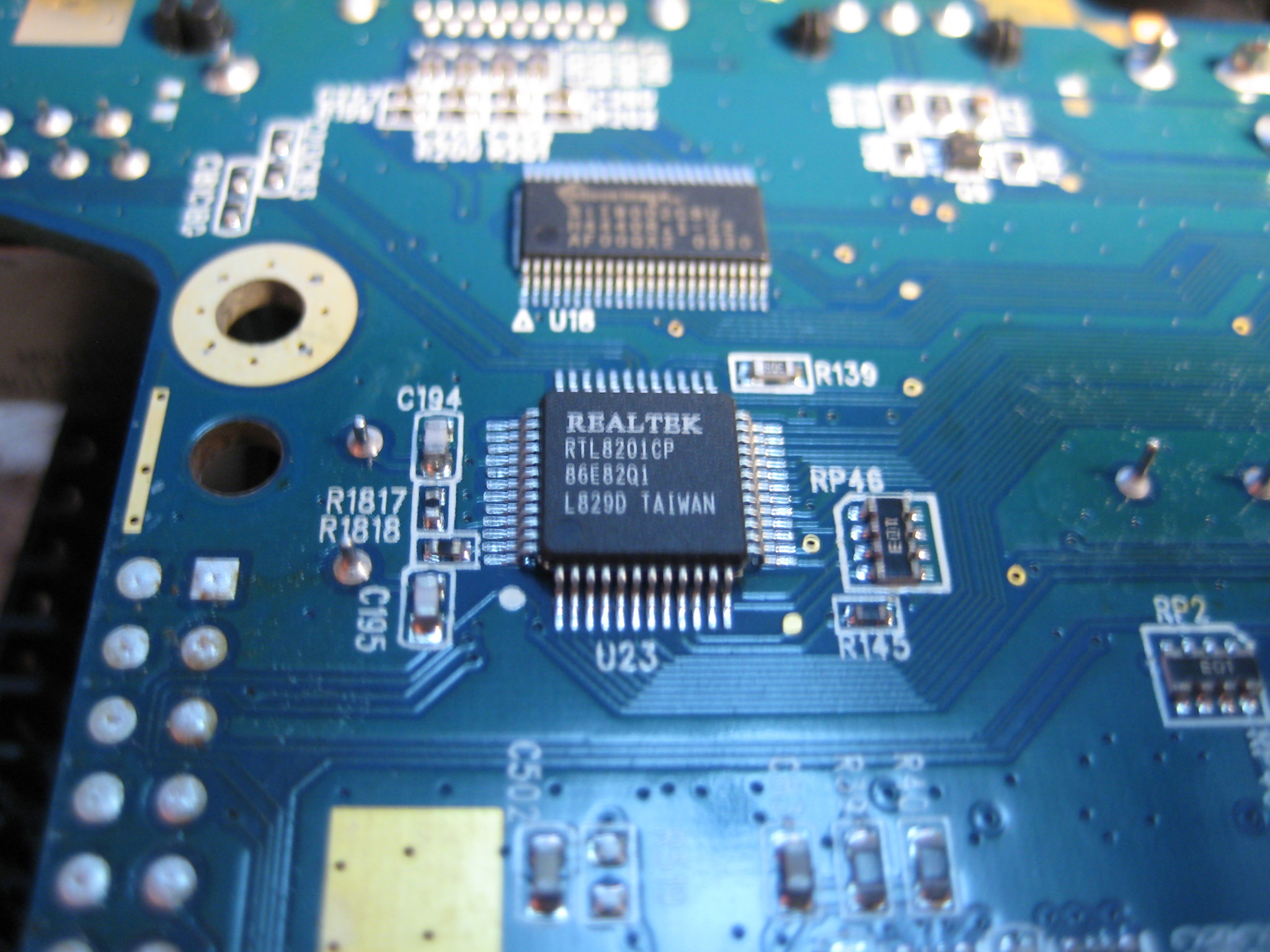
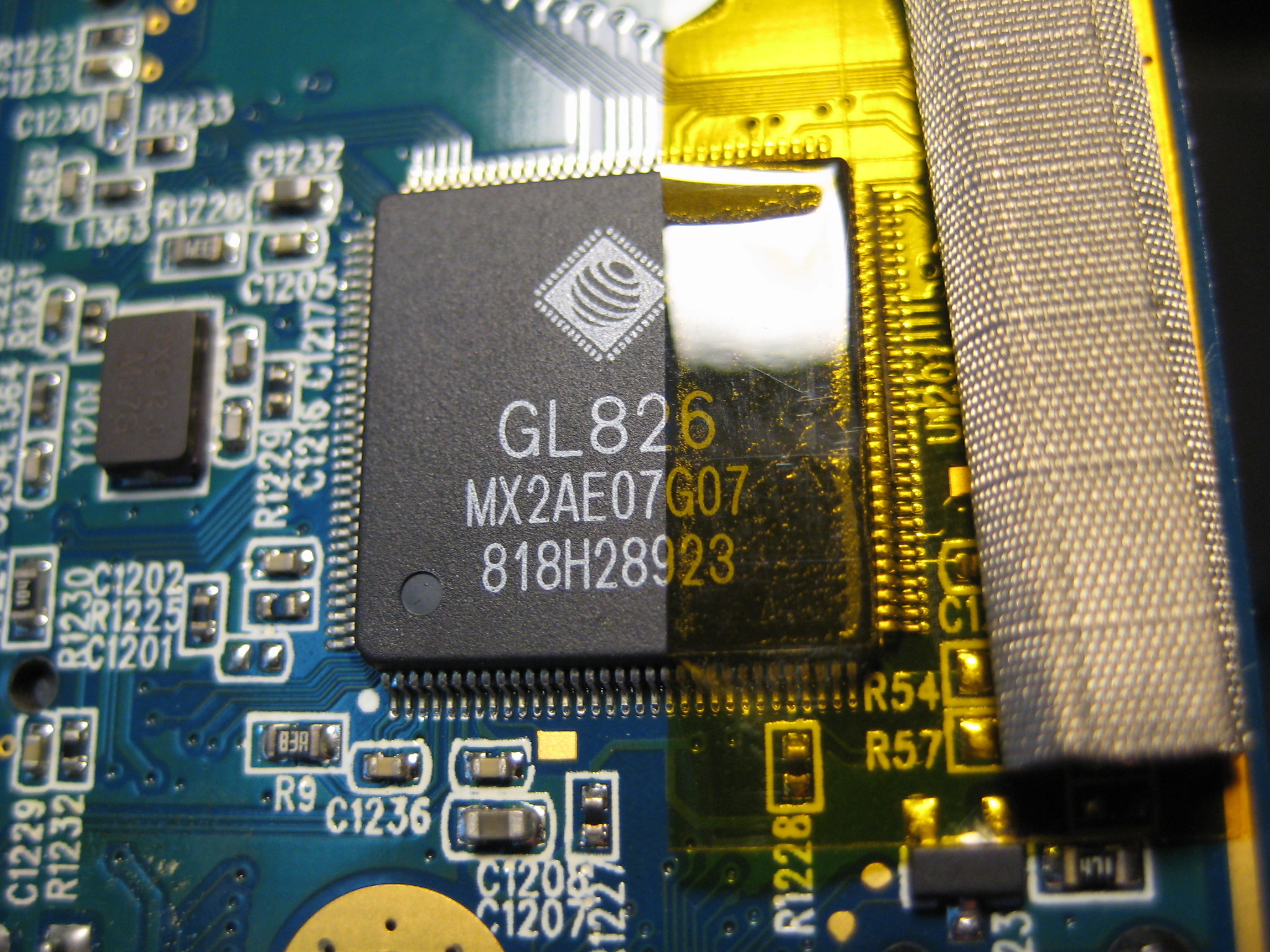 Left to right, a fab date of July 15th 2008, a Realtek RTL8201CP Ethernet port controller, and a Genesys Logic GL826 USB 2.0 "Multi-Slot Flash Card Reader Controller" (datasheet here).
So the good new about this device is that all the peripherals seems to be well documented and fairly common. Realtek and Ralink devices are commonly found on general purpose computers and don't typically require the use of closed source precompiled ('blob') drivers or force users to otherwise jump through various hoops (*coughBroadcomcough*).
Left to right, a fab date of July 15th 2008, a Realtek RTL8201CP Ethernet port controller, and a Genesys Logic GL826 USB 2.0 "Multi-Slot Flash Card Reader Controller" (datasheet here).
So the good new about this device is that all the peripherals seems to be well documented and fairly common. Realtek and Ralink devices are commonly found on general purpose computers and don't typically require the use of closed source precompiled ('blob') drivers or force users to otherwise jump through various hoops (*coughBroadcomcough*).You'll note that I didn't peel the heatsink off the main processor. This is mostly because I loath reapplying heat sink compound. If you're curious to know what kind of processor is in this thing, well, it doesn't turn out to be necessary to take the heat sink off, as we'll see down below. As an aside, I gotta give props to the engineers who made this. It seems really solidly built. The PCB and soldering appears to be of good quality. They used a copious amount of aluminum(?) tape and conductive pads to connect various shields and cover over sensitive wires. The box fits well, nothing rattles. They use parts from big-name companies and only one or two ASIC chips. It seems to have been built more for quality rather than cost.
Probably why the end product cost something around $300 when new. Now, with all the common parts and use of screws, it's almost like they made this thing to be opened and hacked. They even left the reset button populated! Granted each tactile button only costs a couple of cents, but if those buttons get used at all during production I bet it would be less than five times each. Once the board goes in the shield box, that button is never seen again. I suppose it could have been an oversight but I like to think that it might be a nod to the tinkerer who would eventually pop the top on the box.
UART serial port
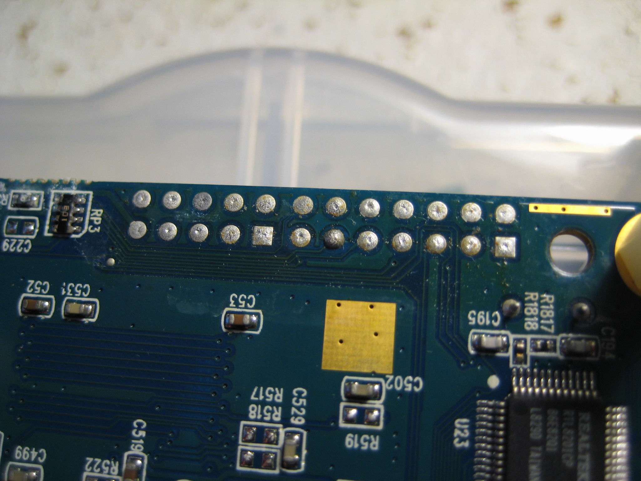
So let's see if we can get root on it! First thing I did was put some hex standoffs in the screw holes so I wasn't knocking some of the smaller surface mount parts off the board when I dragged it around on my work bench. I discovered that these M3 nylon standoffs worked quite well: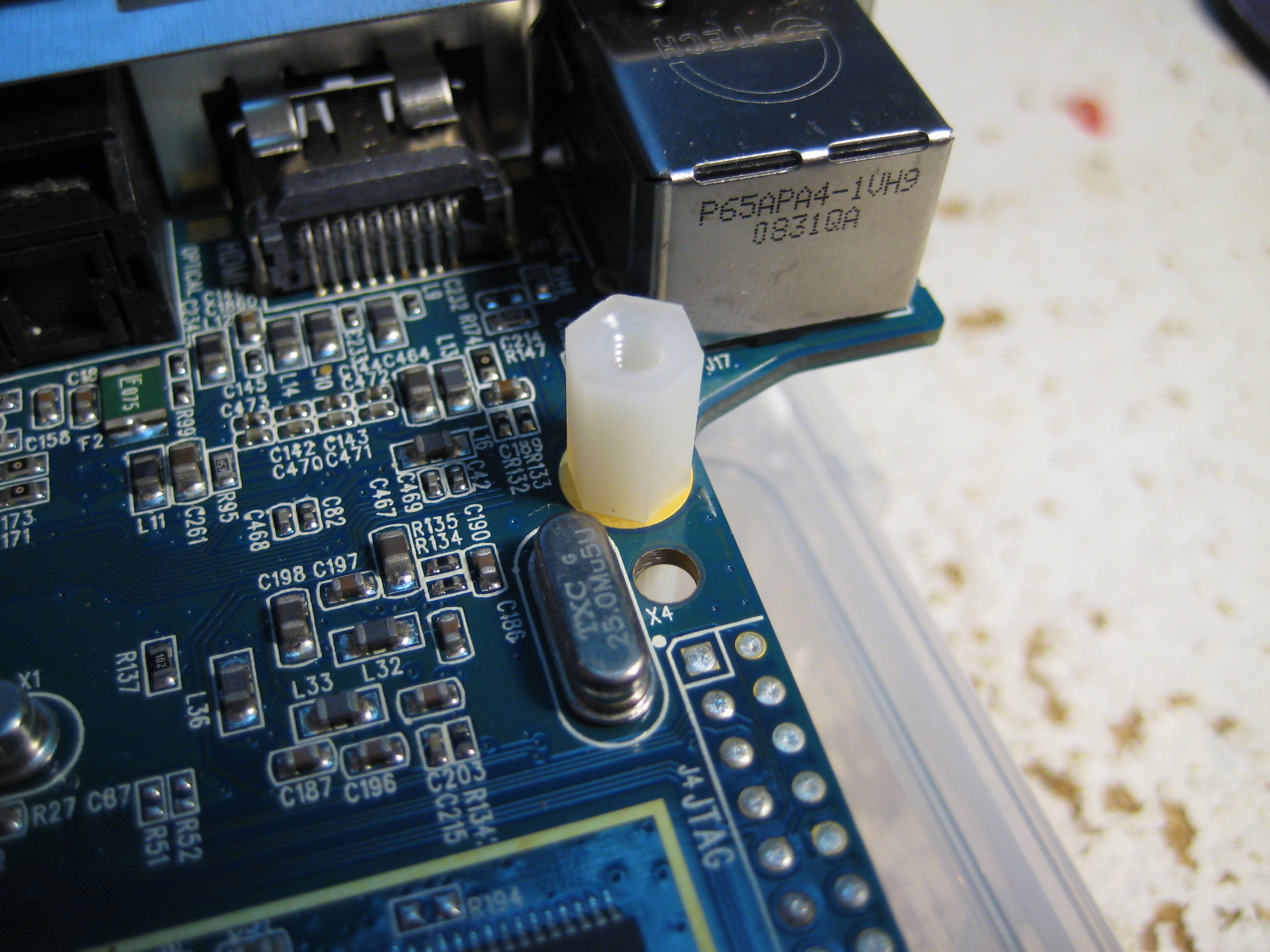 Remember the JTAG and UART header on the board? Here they are again. Photo on the right was with the board flipped left-to-right. Note the location of the square pads.
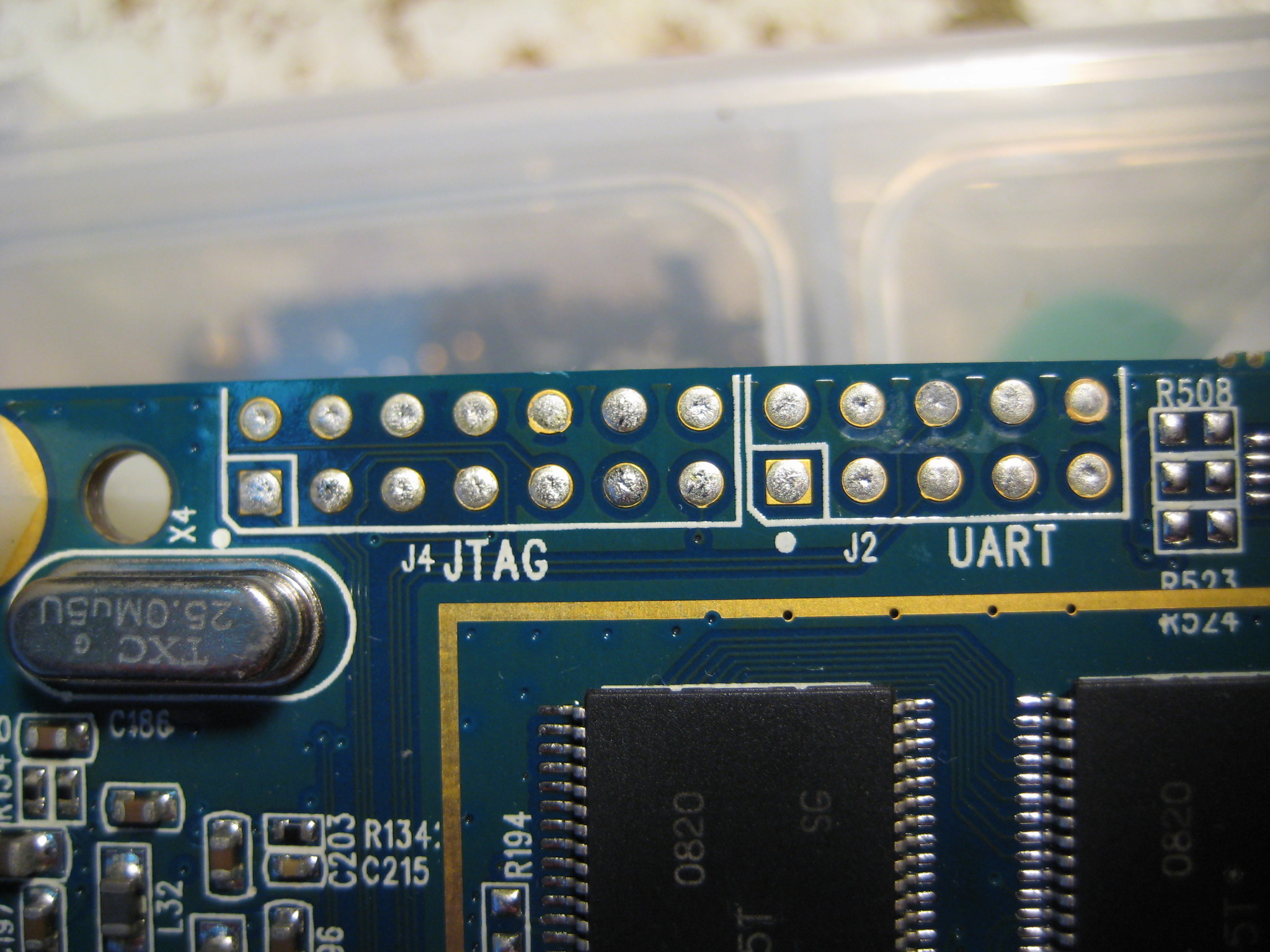
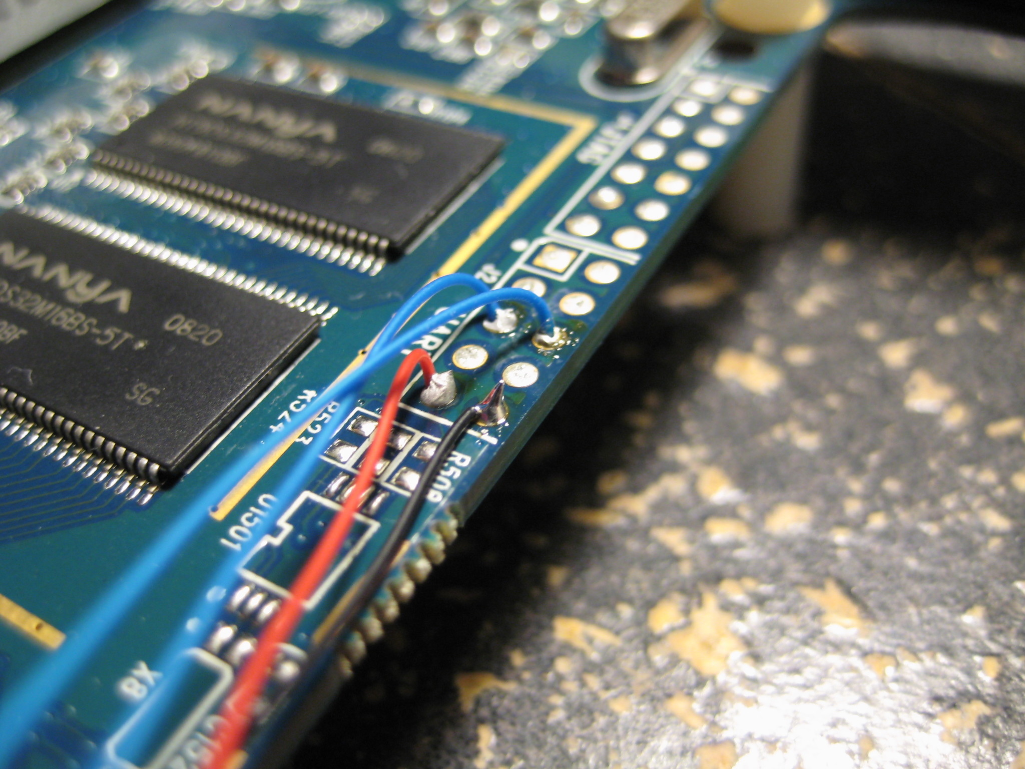
 Turns out most of the pins on the UART header are not connected to anything (at least according to my multimeter skills). Go figure.
The red and black wires are 3.3V and ground, respectively. I think the 'talk' pin (data from the board) is the contact/blue wire farthest away from the edge of the board, but I honestly don't remember exactly. It's the pin that idles high when the board has booted.
Note: The UART (and most of the devices on this board, for that matter) use 3.3V! Using anything higher may break something!
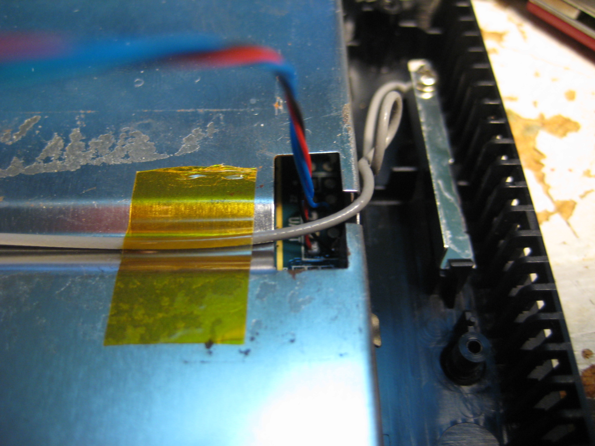
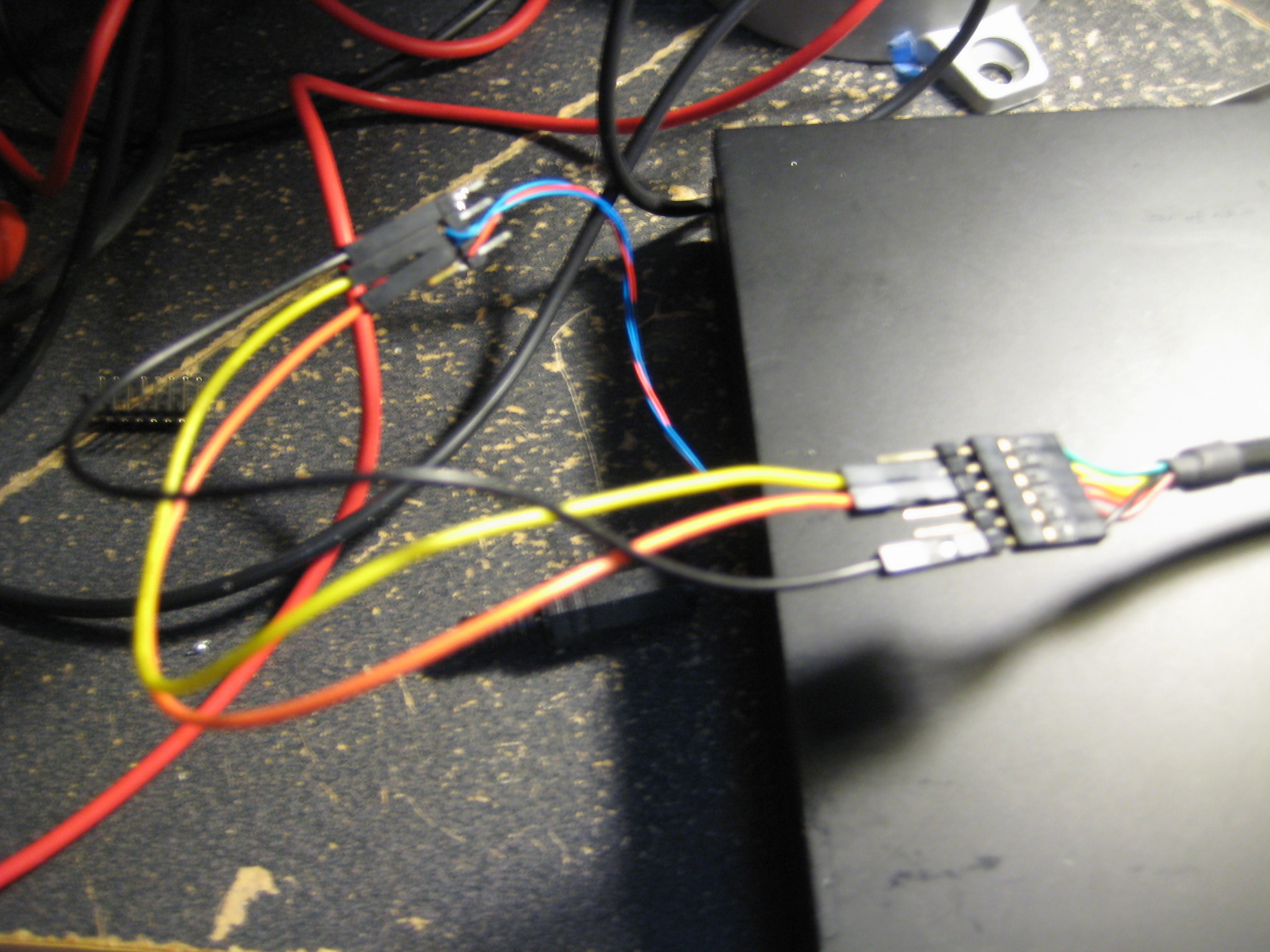
 It seemed a shame to toss the external box and leave the main board kicking around my desk so I reassembled the whole thing. I twisted the serial/power wires together and ran them out a slot in the case. (Good ventilation, Kodak!)
I then cobbled together a power supply using my bench supply and a standard 2.1mm DC barrel plug. My trusty FTDI cable and some jumpers were used to connect to the serial port.
The UART runs at 115200 baud, 8N1 format. This is what you get out of it when you power-cycle it:
xosPe0 serial#d8b3452c0343d4eafdb0130194912ddb subid 0x50 xenv cs2 ok power supply: ok dram0 ok (6) dram1 ok (7) zboot (0) ok > ************************************** * SMP863x zboot start ... * Version: 2.4.0-2.8.0.1 * Started at 0x91000000. * Configurations (chip revision: 6): * Use 8KB DRAM as stack. * Support XLoad format. * Enabled BIST mode. * Enabled memory test mode. * Use internal memory for stage0/1. ************************************** Boot from flash (0x48000000) mapped to 0x8c000000. Found XENV block at 0x8c000000. CPU clock frequency: 297.00MHz. System clock frequency: 198.00MHz. DRAM0 dunit_cfg/delay0_ctrl (0xf3c111ba/0x000c6564). DRAM1 dunit_cfg/delay0_ctrl (0xf3c111ba/0x000b5555). Using UART port 0 as console. Board ID.: "kiwi-groucho" Chip Revision: 0x8634:0x86 .. Matched. Setting up H/W from XENV block at 0x8c000000. SettingWoah! That's a lot of information. So it looks like we know the processor now:to 0x00000100. Setting to 0xff28ca00. Setting to 0x0000c000. Setting to 0x0000009f. Setting to 0x00000000. Setting to 0x0d090800. Setting to 0x10101010. Setting to 0x10101010. Setting to 0x000003fc. Setting to 0x00110101. Setting to 0x000003f3. PB cs config: 0x000c10c0 (use 0x000c10c0) Enabled Devices: 0x0000124c PCIHost Ethernet I2CM USB PCIDev3 MAC: 00:07:5c:11:17:53 PCI IRQ routing: IDSEL 3: INTA(#14) INTB(#14) INTC(#14) INTD(#14) Setting up Clean Divider 2 to 96000000Hz. Setting up Clean Divider 4 to 33333333Hz. Setting up Clean Divider 5 to 25020000Hz. Setting up Clean Divider 6 to 20000000Hz. Setting up Clean Divider 7 to 20000000Hz. GPIO dir/data = 0x600fc000/0x40030000 UART0 GPIO mode/dir/data = 0x6e/0x00/0x00 UART1 GPIO mode/dir/data = 0x6e/0x00/0x00 Generate pulse(s) with GPIO14 .. 0,1(200000us),0 Generate pulse(s) with GPIO15 .. 0,1(1000us),- Generate pulse(s) with GPIO16 .. 1,0(200000us),1 Generate pulse(s) with GPIO19 .. 0,1(200000us),0 Generate pulse(s) with GPIO29 .. 0,1(200000us),0 XENV block processing completed. Found existing memcfg: DRAM0(0x08000000), DRAM1(0x08000000) Heap/Temp/Temp1/Dest start at 0x14000000/0x16000000/0x15000000/0x12000000. Default boot index: 0 Scanning ROMFS image at 0x8d200000 (0x49200000) .. Found. ROMFS found at 0x8d200000, Volume name = MIPS_LINUX_XRPC Found 1 file(s) to be processed in ROMFS. Processing xrpc_xload_vmlinux_ES4_prod.bin (start: 0x8d200090, size: 0x001f6a44) Checking zboot file signature .. Not found. Trying xrpc_xload format .. OK Checking zboot file signature at 0x13000000 .. OK Decompressing to 0x90020000 .. OK (3521559/0x35bc17). Load time total 1059/1713 msec. Execute final at 0x90020000 .. tango2_enet: detected phy at address 0x01 mount: Mounting nodeb on /proc/bus/usb failed: No such file or directory vm.overcommit_memory = 2 vm.overcommit_ratio = 80 /etc/init.d/S70autoexec: Starting application... Using libmodules_install/lib/modules/2.6.15-sigma/llad.ko Using libmodules_install/lib/modules/2.6.15-sigma/em8xxx.ko Installing ralink modules... Using /mnt/app/libmodules_install/lib/rt2860sta.ko Starting mono... found.kernel.core_pattern = /mnt/crashrepfs/%e sendcore = 1 sendreport = 0 host = http://ccr-dev.hcrest.com:8080/ccr/crashpost.do Starting zuibrowser... Please press Enter to activate this console. initializing loop driver
SMP863xThis is part of Sigma Designs "Secure Media Processors" line. They don't appear to make them any more so (of course) their website has no mention of them. (I did manage to dig up this product brochure though.)
CPU clock frequency: 297.00MHz.

System clock frequency: 198.00MHz.
Good to know.
Board ID.: "kiwi-groucho"...
Chip Revision: 0x8634:0x86 .. Matched.Oh. Are we running an SMP8634 then? Maybe I should peel that heatsink off and double check.
  Enabled Devices: 0x0000124c

    PCIHost Ethernet I2CM USB PCIDev3
I2C huh? Interesting. The unpopulated cell holder under the wifi card seemed to suggest an RTC functionality; maybe it's a separate chip.
UART1 GPIO mode/dir/data = 0x6e/0x00/0x00I wonder if that is available on a header somewhere.
Scanning ROMFS image at 0x8d200000 (0x49200000) .. Found.

ROMFS found at 0x8d200000, Volume name = MIPS_LINUX_XRPC
So it's not ARM, it's a MIPS core. That...might be an issue from a 'I want to write software for it' standpoint.
Processing xrpc_xload_vmlinux_ES4_prod.bin (start: 0x8d200090, size: 0x001f6a44)Now we're running across things that might be useful later on. It also seems to suggest that Linux was used and not something like VxWorks. There are various other lines that give us hints about what's loaded on the system, including a list of modules being loaded and the location of a/the startup script:
/etc/init.d/S70autoexec: Starting application...
This is particularly interesting:found.kernel.core_pattern = /mnt/crashrepfs/%e
sendcore = 1 sendreport = 0 host = http://ccr-dev.hcrest.com:8080/ccr/crashpost.doSome kind of crash log collection system? The URL doesn't go anywhere and hcrest.com goes to a Microsoft Exchange web interface. A WHOIS lookup doesn't give anything useful either, they're using a privacy proxy service. The Archive.org Internet Wayback machine, however, shows that back in 2006 the webpage was owned by an organization called Hillcrest Labs. You can see (what remains) of their webpage here. They were using a flash interface as their front page so the web archive was unable to grab anything useful (*silent, frustrated screaming*) but the main image on the page looks interesting. In fact I'd say it looks like some kind of gripped pointing device:

 Remember, this was back in 2006 when the Nintendo Wii was making waves with it's "motion controls" and MEMS devices were hot stuff. Everybody and their grandmothers were coming out with gyro/accelerometer hardware and accessories. Perhaps it's not a coincidence then that the Kodak Theatre HD Player used a "gyro remote":
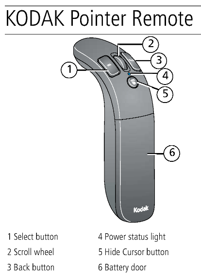
(Take from page six of the KODAK Theatre HD Player Extended user guide.) I had a long winded theory here about how Hillcrest Labs was bought out by Kodak for their motion control tech, but then I did a Google search and found that they probably just changed their website address: hillcrest.com.
Oh well. My story was cooler.
Please press Enter to activate this console. initializing loop driverSadly, pressing enter just repeats 'Please press Enter to activate this console.' We're going to need to find another way in.
Networking
Let's see if we can do something with that network port. Maybe they left something open. Fortunately it seems to work with DHCP out of the box. I plugged it into a switch and checked my DHCP lease table:KODAKHDTHEATRE / 10.0.0.12 / 00:07:5C:11:17:53 / wiredExcellent. Okay
nmap, do your thing.[user@localhost ~]$ sudo nmap -p1-65535 10.0.0.12 Starting Nmap 6.47 ( http://nmap.org ) at 2016-01-14 11:09 PST Nmap scan report for 10.0.0.12 Host is up (0.00094s latency). Not shown: 65526 closed ports PORT STATE SERVICE 80/tcp open http 8888/tcp open sun-answerbook 44000/tcp open unknown 44001/tcp open unknown 44002/tcp open unknown 44003/tcp open unknown 44004/tcp open unknown 44005/tcp open unknown 44006/tcp open unknown MAC Address: 00:07:5C:11:17:53 (Eastman Kodak Company) Nmap done: 1 IP address (1 host up) scanned in 5.04 secondsI also scanned for open UDP ports. This took a lot longer, so I didn't scan the entire range:
	Not shown: 999 closed ports
	PORT     STATE         SERVICE
	1900/udp open|filtered upnp
	MAC Address: 00:07:5C:11:17:53 (Eastman Kodak Company)
Port 80, huh? Let's take a look:
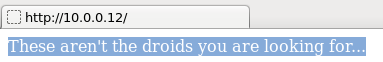
Har har.
We don't know if there are any other files in the server root directory, nevermind their names, so there is no point in trying to guess URLs. I've seen Port 8888 used as a webserver port occasionally, but this time nothing much happened when I tried to load it via a web browser.
Using
telnet was much more effective:[user@localhost ~]$ telnet 10.0.0.12 8888 Trying 10.0.0.12... Connected to 10.0.0.12. Escape character is '^]'. Connected to ZDB Server (type \help for help)... jsConsole:> jsConsole:>\help Commands: \refresh: refresh the current scene \gotoRootBased on what we see when we dissect the firmware (farther down), I strongly suspect this is proprietary software created by Hillcrest Labs. Specifically, I think it's the back end of their GUI system. As far as I can tell there isn't any documentation to be had, so this is pretty much a dead end.: goto a root path \gotoZui : goto a zui path \help: ask for help \quit: quit the console Inline Script Evaluation: Just enter a normal line of javascript in order to evaluate it in the current document. jsConsole:>
There are, of course, security concerns with having what appears to be the primary command interface for your entire system available to everybody on the network, but I'll leave that rabbit hole to the professionals. The only other thing of note with this port is if the user enters
CTRL-D at the console:jsConsole:>eval:>Javascript Dynamic Evaluation Exception: Error compiling or executing Javascript file 'file:////mnt/app/apps/hcrest.ux.common/screensaver/bounce/bouncingImage.svg'The other ports are fairly boring. Ports 44000 to 44006 don't appear to do anything. I suspect their some kind of media streaming port; if anybody has information I'd love to hear it. Port 1900, UPnP, is a fairly standard service so I didn't mess with it at all.
Capturing the Firmware
So what now? Well, let's see if we can get our mitts on the firmware. If we can't get access by default, maybe we can get access by writing our own firmware to the system.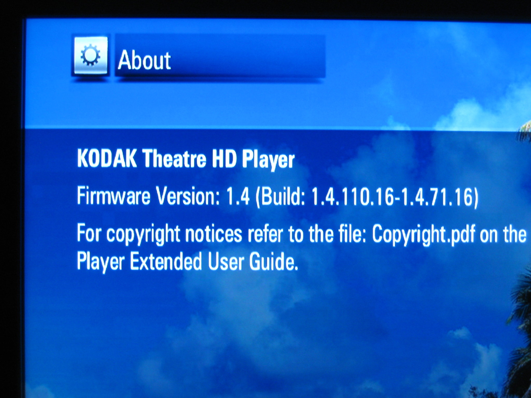
So I finally plugged the box into a monitor.
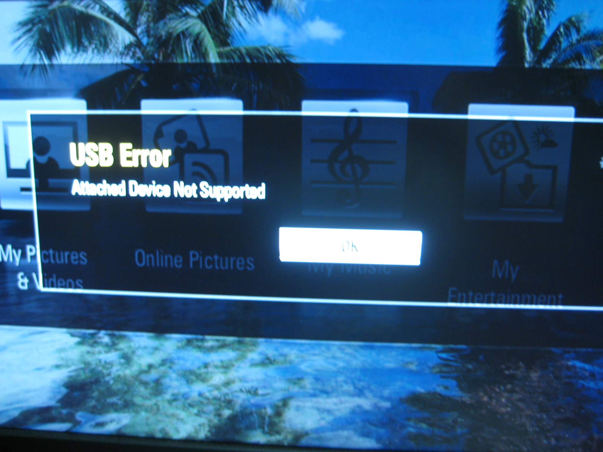
Disregard that. Turns out you can plug a mouse into the front USB port and the on-screen pointer works fine! Go figure. I had naively hoped that there would be a menu option somewhere that would let me backup the system firmware somehow, but no such luck. Neither was there any obvious way to update the firmware from a memory card or USB thumb drive, but there is an option to download an update from the 'net. My plan now was to plug Wireshark in between the box and the network and snag all the traffic that was generated when I ask the box to check for updated firmware. I hoped that would give me a URL to a firmware blob that I could dismantle. There was also a possibility that I could set up a server on a closed network to pretend to be the Kodak firmware server so I can push my own firmware into the system - a trick I dimly remembered seeing used a long time ago. I used my laptop as a gateway and DHCP server. It's WiFi card connected to my home network, while the Kodak STB plugged into the Ethernet port. Fire up Wireshark, click that 'Check for Updates' button in the Settings->System panel, and the box requests the following URL:
http://dmpfw.kodak.com/aus/req?Request=["softwareUpdate"/"getUpdate"/"EKMediaPlayer"/"1_4_36"/"sigmaVantage"/"en_US"/"kiwi-alpha"/"d8b3452c0343d4eafdb0130194912ddb"]Note that the User Agent string the box uses when sending the request contains the firmware version currently installed. In my case that string is:
HC/1.4.110.16(Some testing with
wget while modifying this string didn't seem to do anything, so it's probably just for logging purposes.)
What happens if we change the "1_4_36" to, say, oh I don't know, "1_1_36" and then send the request ourselves?(Note that
wget prefers the URL in the following format:http://dmpfw.kodak.com/aus/req?Request=[%22softwareUpdate%22%2c%22getUpdate%22%2c%22EKMediaPlayer%22%2c%221_1_36%22%2c%22sigmaVantage%22%2c%22en_US%22%2c%22kiwi-alpha%22%2c%22d8b3452c0343d4eafdb0130194912ddb%22])We get back this:
{"extent":"complete","hashValue":"8e84dd28230c26482d62a8b33dd5fe02f0860e71","hashFunction":"sha1","URL":"http://download.kodak.com/digital/software/theatreHDPlayer/EKMediaPlayer-1_4_36.fw","type":"minor","size":39173597,"version":"1_4_36"}
Victory! The firmware can be downloaded from Kodak from the the following link: http://download.kodak.com/digital/software/theatreHDPlayer/EKMediaPlayer-1_4_36.fw
And before anybody bothers, I threw together a quick perl script to ask the server for every permutation of the firmware version numbers, but got nothing back. Oh well.
So out of curiosity I plugged the firmware name into Google and found this post on Woot.com, of all places.
In it, user Jokipix claims to be a Hillcrest Labs engineer and gives some (probably unauthorized) tech support for this unit, up to and including handing out replacement units! S/He also give us this little nugget of information: "If you manually download that file, put it in the root of a USB drive, and insert it into a running Kodak HD Theatre it will update from the USB directly." Good to know. There might be some other juicy technical nuggets buried in that thread, but honestly I haven't read the whole thing. (Yet?)
Dismantling the Firmware
This was outside my skill set and was somewhat daunting when I started, but thanks to some nifty tools it turned out to be relatively straightforward. I highly recommend this five minute tutorial by one Craig; it will introduce you too the basics. It's from 2011 and is based around the firmware for the Linksys WAG120N (haha, 'wagon') router, but the techniques and utilities are still relevent. We'll be making extensive use of the Linuxfile utility. We throw a file at it, and this neat little program tries to determine what kind of file it is.So, we have the original firmware file from Kodak:
EKMediaPlayer-1_4_36.fw.The
file utility tells us it actually a gzip file: gzip compressed data, last modified: Thu Apr 30 10:46:21 2009.Decompress it like so:
gzip -kd EKMediaPlayer-1_4_36.fw
The resulting file is now somewhat confusingly named EKMediaPlayer-1_4_36.fw. (I added .gz to the original file I downloaded from Kodak to differentiate it.)Running the
file utility on the new EKMediaPlayer-1_4_36.fw returns: EKMediaPlayer-1_4_36.fw: cpio archiveLucky for me, "Engrampa" (archive manager for MATE on Fedora 21) can open
cpio archives. The resulting file structure is as follows (size in bytes and filename):37224448 application.romfs 2097152 app-zbimage-linux-xrpc 7 duration 3037 inner.sh 11 storexenvs 7 version 1 xenvs 1250 xenvsutilNot quite what I was expecting. I guess the box unpacks the archive and then runs those shell scripts? Let's take a look at that
inner.sh file that is in there.Turns out this script is a complete goldmine of information. It appears to be a script that is used by the system to actually write binary files to flash and it has information on internal utilities (
progflash) and block device names (/dev/mtdblock6, /dev/mtdblock7) and points to the two files which apparently store both the operating system (app-zbimage-linux-xrpc) and the 'applications' (application.romfs).
Let's see what the file utility returns:
app-zbimage-linux-xrpc: romfs filesystem, version 1 2058976 bytes, named MIPS_LINUX_XRPC.

application.romfs: Squashfs filesystem, little endian, version 3.1, 37195800 bytes, 6530 inodes, blocksize: 131072 bytes, created: Thu Apr 30 10:45:41 2009
Fedoras Disk Image Mounter will mount romfs file systems just fine. All that is contained in app-zbimage-linux-xrpc is another file: xrpc_xload_vmlinux_ES4_prod.bin. Not sure what format it is in. Dead end for now.
The other file, application.romfs, is much more interesting. The Squashfs filesystem is commonly used in embedded devices, and the Linux community has provided tools to work with this format:[user@localhost firmware_files]$ unsquashfs application.romfs Parallel unsquashfs: Using 2 processors 5223 inodes (5547 blocks) to write [=================================================================================================================-] 5547/5547 100% created 5221 files created 1307 directories created 2 symlinks created 0 devices created 0 fifosAnd we're in. There is lot's to look at; including stuff like the entire user interface and associated files. I poked around a bit and found something of interest: In
update.sh, in the root directory, we find this line:# If something happens during install - boot into the manufacturing kernel setxenv -f /dev/mtdblock1 -k z.default_boot -b -v 1And later:
	# Install worked so set default boot back to normal
	setxenv -f /dev/mtdblock1 -k z.default_boot -b -v 0
So there appears to be some kind of emergency/factory bootloader stored in 'block 1' of flash? I'll need to look into that later. If you're still keeping track, though, we still haven't gotten to a root terminal. Maybe I can do something with the firmware to give me that capability?
Bricked! (Plus some JTAG work)
Yup, I bricked it. I had modified a few files in the interface (background images) just as a proof of concept that the system could be updated at will.(It can, by the way - the internal update software seems to key off of the version number contained in the file name of the firmware package, not any particular file actually stored in the package. In this way one can update the system an indefinite number of times by simply naming their custom firmware package so it has a higher version number than the version that it actually installs.)
I didn't realize that the SquashFS file system changes for every release, and the tools I had installed from the Fedora repo were for version 4.0. So I packed up my custom firmware, used the built in firmware updater to upload it, rebooted, and got this:
	[snip]
	Processing xrpc_xload_vmlinux_ES4_prod.bin (start: 0x8d200090, size: 0x001f6a44)
	  Checking zboot file signature .. Not found.
	  Trying xrpc_xload format .. OK
	  Checking zboot file signature at 0x13000000 .. OK
	  Decompressing to 0x90020000 .. OK (3521559/0x35bc17).
	  Load time total 1059/1713 msec.
	Execute final at 0x90020000 ..
	tango2_enet: detected phy at address 0x01
	mount: Mounting nodeb on /proc/bus/usb failed: No such file or directory
	vm.overcommit_memory = 2
	vm.overcommit_ratio = 80
	SQUASHFS error: Major/Minor mismatch, trying to mount newer 4.0 filesystem
	SQUASHFS error: Please update your kernel
	mount: Mounting /dev/mtdblock7 on /mnt/app failed: Invalid argument
	/etc/init.d/S70autoexec: hc.autostart enabled, but autoexec.sh not
Whups! Well, that's an easy fix, right? I just use the older tools to build the filesystem, repackage everything, and update the firmware again.
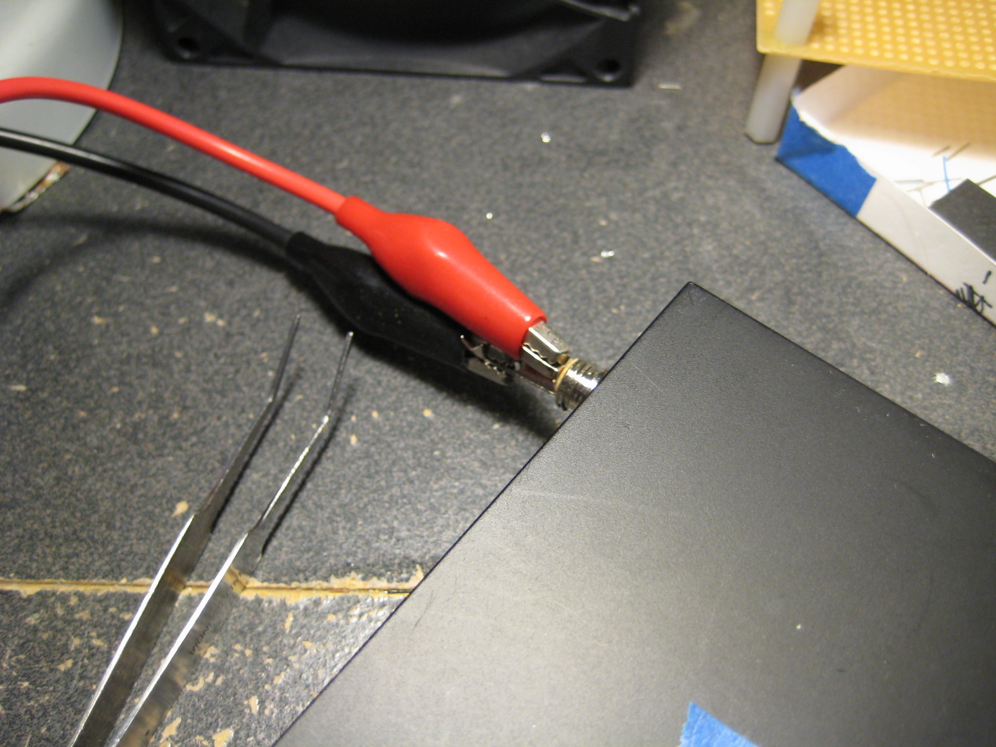
Well, no. The update scripts are in the applications section of the system - the section of the system that uses SquashFS. Now that that 'disk' doesn't load, I have no obvious way to rewrite the flash. Enter JTAG! (Well, technically, the JTAG Test Access Port, but everybody just calls it a JTAG port.) Sadly, the pins weren't labeled.
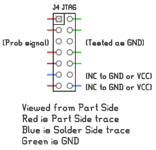
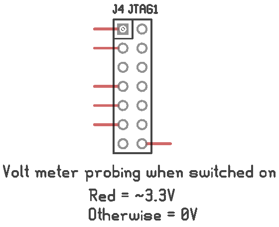
In the first image, the green traces were obviously ground - they were attached to the ground plane. I wasn't too keen to shoot the 12 V from my multimeters continuity testing mode through potential data pins of a 3.3 V processor, so I only tested a couple of pins to see if they connected to ground or the 3.3 V rail: the third pin down on the left and right side, and the two pins on the bottom right.
The footprint was looking a lot like this de facto standard footprint often found on MIPS-based routers:
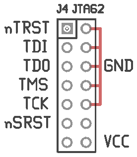
Unfortunately it wasn't a match. It was close enough that I thought I could make an educated guess. I probed around a bit with a JTAG cable and some jumpers but didn't get anything to work. So, that's pretty much it. The serial terminal doesn't let me enter commands, I never figured out how to enable the factory bootloader mode without the application filesystem being intact, and the JTAG port looks like a dead end. I can't see any way of updating the firmware now, short of desoldering the flash chip. I'm going to shelve it for now, maybe in a year or two I'll know more and be able to take another stab at it.