

CNC Table
Building some kind of CNC tool base has been in the back of my mind for a while, and over the years I had amassed most of the critical parts either through luck or by jumping on sales as I saw them.However my plans were always hamstrung by the cost of parts - practically all hardware stores (like McMaster, Grainger, MSC) sell linear bearing, pulleys, and what-not for rather fantastical prices. Admittidly I'm not a mechanical engineer, but these numbers seemed outlandish for things that looked like chunks of aluminum or acetel with the occasional collection of steel balls. As a hobbyist these prices limited my toolset significantly - I don't have the budget to drop ~$75 per bearing, particularly when I'll need at least four of them.
The moment of critical mass was when I saw Adafruit was carrying relatively inexpensive linear bearings and related hardware. A price of $7 per pillow block/bearing compared to the $50 each for an identical part from McMaster was all the incentive I needed to place an order and get serious about the project.
[ 2013-08-06 ]
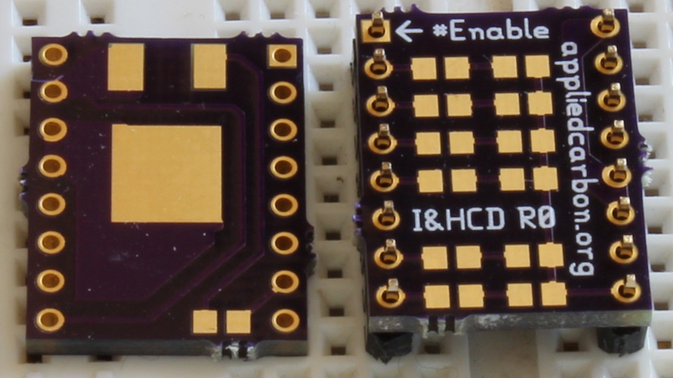
I had a stepper motor controller board in production well before I started this project. It was a design intended for a separate project but designed to be multipurpose:
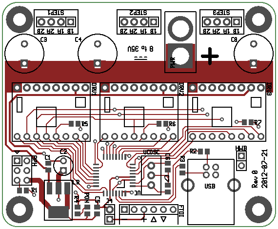
I had a number of idea for projects that could benefit from a robust stepper motor controller. It was designed around three of Pololus Allegro A4988 Stepper Motor Driver Carriers, a design choice inspired by an open source CNC laser project over at buildlog.net. (I even figured out who made those heatsinks, or makes similar ones anyway: they appear to be EnzoTechs MOS-C10.)
My design differed significantly in that it had pin-outs for both USB and serial facilitated by an on-board microcontroller, an Atmel ATMega32U2. Or it would have, if I could have gotten the 32U2 to actually work: Of the two chips I used, one wouldn't respond at all to the programmer while the other one would report its part number (after some fiddling) but could never be programmed successfully. Either they're super sensitive to ESD, Digikey had a bad batch of chips, or avrdude doesn't actually support the part for whatever reason. What to do? I had a $30 board sitting on my workbench that was perfectly usable except for the microcontroller, of which no pin compatible parts existed (AFAIK).
Well, I did this:
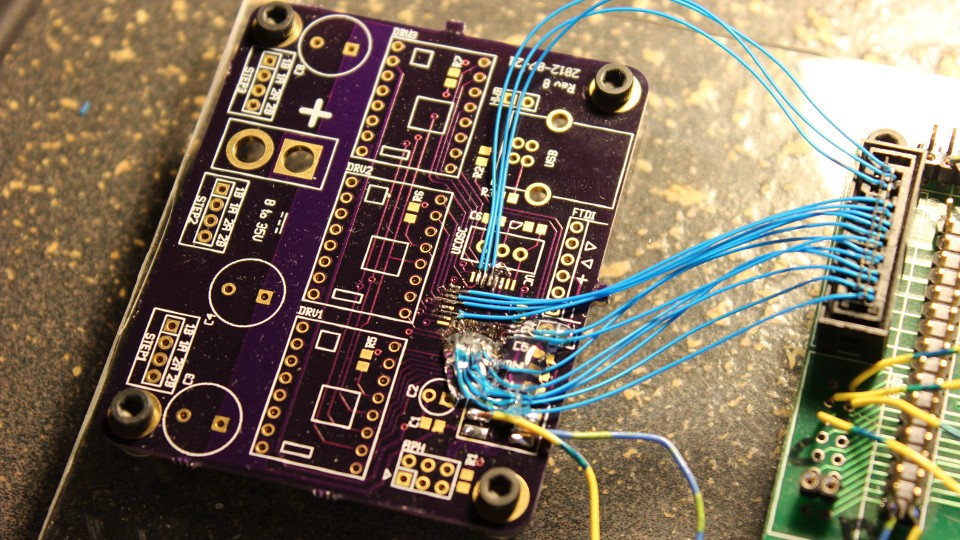
That's 30 guage Kynar wire-wrap wire and I'm soldering individual strands onto 0.060"x0.015" solder pads of a TQFP-32 7mm footprint. The green board to the right is a third-party Parallax Propeller chip development board.
I ripped the top off an IDC 0.1" pitch plug and pushed the wire into the wire capture forks. I bolted both boards to a piece of scrap acrylic to keep everything stable and used copulas amounts of hot glue to keep the solder joints from breaking.
The A4988 drivers are pretty much self-contained, requiring only power and a few passives to operate. A few notes on the design: The #Sleep pin on the drivers is pulled high internally so I left that disconnected for all the drivers. The microstepping selection pins are actually all on the same bus; this was done entirely because I was running out of pins on the microcontroller. The #Reset line is pulled low on each driver by an external 10k ohm resistor; this keeps all the drivers disabled by default until the microcontroller deliberately turns them on.
Here is what it looks like, all assembled:
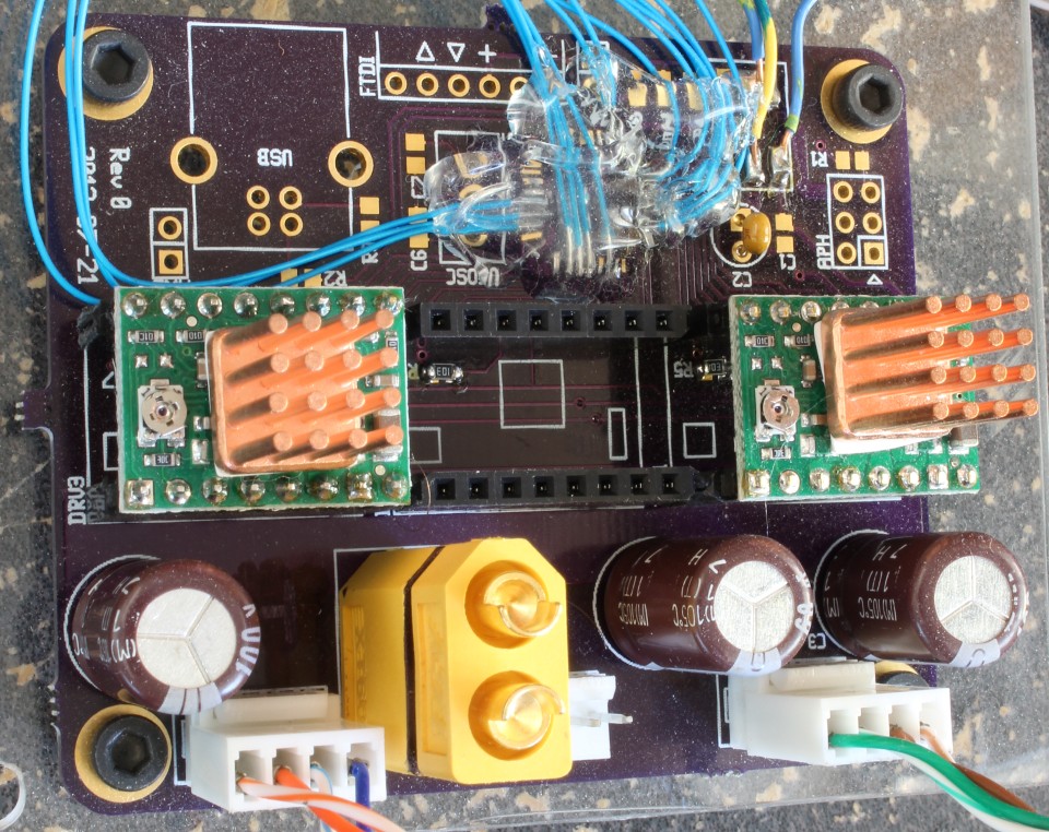
(Pardon the dust. And the hair.) The bulky yellow thing is a Hobbyking/hexTronik XT60 power connector, a polarized, patent-free, low cost connector capable of handling 60 amps continuously. It's a part I desperately wish they'd make PCB-friendly variants of.
...and it's actually soldered on backwards in these photos. Oops. I'm using a repurposed Dell 130W laptop power supply (model PA-1131-02D), delivering 19.5VDC at 6.7A. If you chop the plug off one of these you'll find three wires: a thin central conductor running though a thicker bundle, and an outer 'shield' bundle. The thin wire right in the middle is a communication line (I think it's Maxim/Dallas 1-Wire protocol?) to a read-only memory inside the power supply that identifies its output rating to the laptop it's plugged into. The outer bundle is the main ground line and the middle bundle is the positive terminal. Keep in mind that the polarity of the connector the photo here is backwards (the ground line is attached to the connectors positive pin and visa versa).
[ 2013-08-27 ]
One of the things missing from both of these boards was any kind of status indicators or debug display. I had a spare socket on the driver board (I haven't even thought about implementing a Z axis yet). At the same time I was trying to figure out how to drive large loads. Eventually I'd want to hook up solenoids, or rotary tools, or maybe even a laser and I'd like to control these tools from the same board, if possible. I ended up combining six LEDs and a DPAK footprint for an N-Channel Enhancement mode MOSFET on a board with the same footprint as the motor drivers:
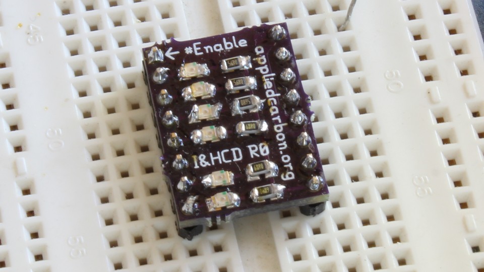
The output pins are wired so raw power is available on one side and the MOSFET drain is on the other. The Propeller chip starts with all its outputs pulled low, so the MOSFET starts in the high-resistance state. The gate drive voltage is a bit low (only 3.3V) since it's coming directly off the Propeller chip but hopefully it will be enough to be useful. If I rework the design later I'll probably put a BJT on the gate and tie it to the raw power supply bus so we can get an even lower 'on resistance' through the MOSFET. Or I may just replace it with a mechanical relay.
The LEDs are connected to the shared microstepping bus (thus letting the user know what mode the drivers are in) as well as connected to the sockets #Reset, Step, and Direction pins, which give the programmer a number of LEDs to use to indicate status or just blink wildly.
[ 2013-08-29 ]
I don't own a machine shop so this would arguably be the hardest part of the project, or at least the one where I'd learn the most. A significant amount of effort went into designing the system such that it could be fabricated in a generic garage with almost no special tooling - an important consideration given that the only power tool I have access to is a drill press. Consequently I've given the design a lot of thought.
Generally speaking, from the standpoint of motion, there appears to be two types of CNC machines:
- Moving head, where the 'head' or tool of the system moves in the various axies, and...
- Moving table, where the workpiece is moved as needed.
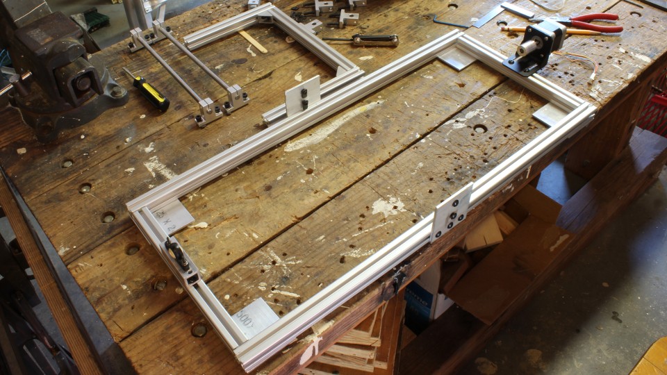
In my case, a 'pure' system of either type is not ideal - I'm not aware of any designs at these extremes that are easier than hybrid setups. On a similar note a two axis head design seems difficult, particularly the bearing layout, and the two axis table requires a larger footprint than a one axis/gantry design (for a given table size). Thus, I went with a table running on a single axis (which I tend to arbitrarily refer to as the X axis in this document) under a gantry which implemented a tool carriage on the Y axis. The Z axis will be address when (if) I get to the stage where a 3D printing head would actually be useful. A failed/canceled project had left me with a sizable pile of 20mm square T-slot extrusion (often referred to by the trade name "80/20").
And thats how I decided on my frame size. :D
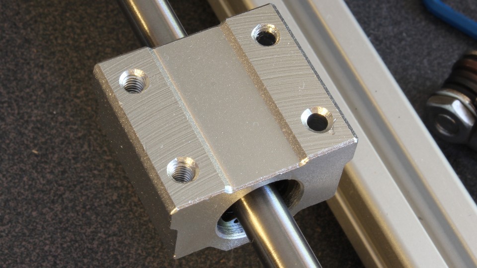
 As it turns out, an 8" square plate fits nicely inside the frame so I added a 8"x8"x0.25" 6061 aluminum plate to my McMaster order, as well as a countersink drill bit and some M4 316SS flat head bolts to attach the plate to the linear bearing pillowblocks:
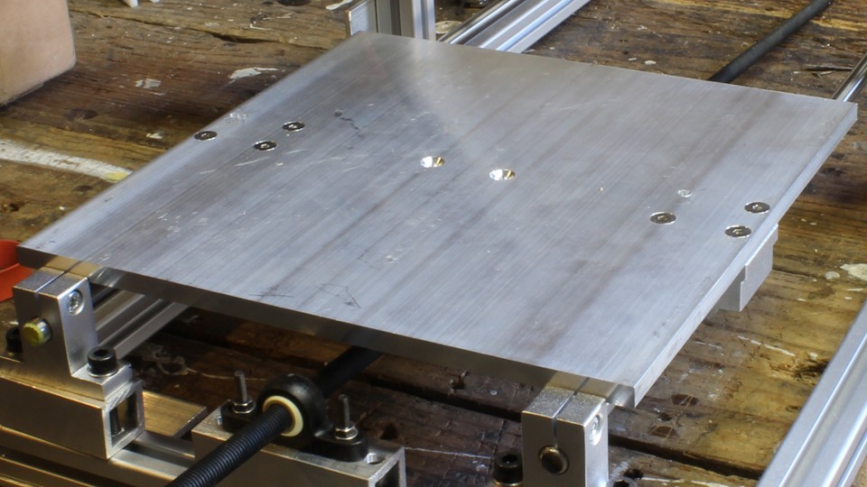
(Misdrilled holes? What misdrilled holes? *nonchalant whistling*) The Adafruit parts were mostly based around a shaft size of 8mm and here I ran into another problem. Eight millimeter hardened and precision ground shaft isn't inexpensive: around $28.90 a meter, and I'd need at least 1.75 meters of the stuff. After some flailing and some browsing of the raw materials section of the McMaster catalog I stumbled across precision ground O1 Tool Steel (also know as drill rods). Surprisingly it was the cheapest stuff in the section at about $6.23 a meter, and with a hardness of Rockwell B89 (versus C59-C65 for the purpose-made shafts and B83 for the 316 Stainless Steel variants). I decided to take a chance on it and I'm happy to report that it is working out quite well (so far). I picked up a collection of 'small' (actually medium size, according to the manufacturer) SC8UU pillow blocks (which included LM8UU 8mm linear ball bearings. In retrospect, I wish I hadn't used these parts. Out of four pillow blocks ordered, one arrived with half it's mounting screw holes unthreaded, and another with a bearing that barely moved and scraped up the shaft:
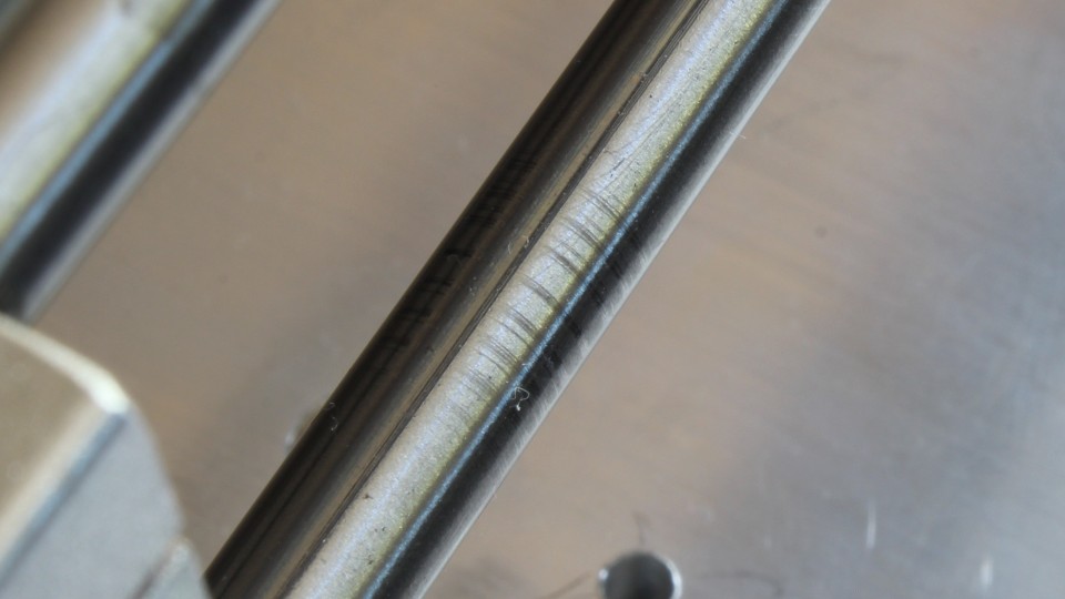
The movement of the remaining ones don't feel as smooth as I'd expect and don't make the most pleasant of sounds either - they sound a bit like somebody pulling a sword out in a bad action movie. If you dig around online you'll find I'm not the only one with these issues. If I was doing this again I'd probably give sleeve bearings a shot. An alternate solution would be to grab a cheap UHMWPE cutting board from Wallmart or similar and fabricating some 'slider pads' from that. Happily the SK8 shaft guide/supports and corner braces I ordered are perfectly functional. Here's an annoying 'gotchya': McMaster T-slot parts are based around M5 bolts while Adafruit parts are designed with M4 bolts in mind. Most of the time mounting holes are big enough to accommodate M5 screws (thankfully, since I have a giant bag of them) but the Adafruits NEMA-17 stepper motor mounts are designed specifically for M4 bolts. The paint job doesn't help any and in fact it reduces the interior diameter of the central motor support hole enough to prevent stepper motors from fitting.
Nothing that ten minutes with a couple files and a bench vice won't fix, but still annoying. I'm using a set of bipolar stepper motors, Type 103H548-4946 made by Sanyo Denki, Lot Number 05306. They have a step of 1.8 degrees, a coil resistance of 1.6 ohms, and 5mm circular shafts. I haven't been able to dig up a datasheet for these motors, but given their size and similarity to other Sanyo Denki motors I'd found I'd guess their rated current is one amp.
I picked these up on a whim from Allelectronics a while back and they've just been burning a hole in my parts box since; feels good to get them out and into a project.
As an aside, if you're looking for parts for a one-off or hobby project, I highly recommend hunting for motors in surplus shops. You can often get decent name-brand motors for far cheaper than you would get the same parts new, and often they'll come prepped with electrical connectors and belt pulleys.
If, for whatever reason, you want to buy new I highly recommend Pololu - they have a fantastic selection, reasonable prices, and everything is well documented. So how do we make these motors drive the table on the X axis and the tool carriage on the Y axis gantry?
I had a couple of options. We have the classic leadscrew where a rotating threaded shaft pushes a captive nut back and forth, various drive belts systems, and the somewhat unusual wire/string/monofilament and pulley system that I've seen used in simple homebrew machine and some desktop scanners.
The filament/pulley system is attractive because the connection between the motor and whatever it's driving is light, flexible, small, easily adjusted and attached, and doesn't tend to exert strain in odd directions. However, finding metric rotary drive components in the US is an exercise in frustration. Pulleys seem like parts that one can turn off on a lathe from stock pretty quickly, but it's been years since I used a lathe and I don't have access to one anyway.
Timing belts are very popular and are used all over the place. Despite this I once again ran into the exorbitant prices that seem to be endemic to this industry, as well as a lack of support of metric sizes that is typical in this country. Prices appear to start at about $10 each and only go up from there. Adafruit has a selection of GT2-type pulleys for 5mm and 8mm shafts that are as cheap as I've found them anywhere. I settled on using leadscrews. Metric threaded rods are dirt cheap, easy to source, and have sufficient thread-fit for my purposes:
I picked up some flange nuts with the idea that I could epoxy or even hot glue them to some right angle brackets I'd make out of aluminum right-angle stock that was (literally) gathering dust in a corner. I also picked up a couple of Adafruits 5mm to 8mm aluminum flex shaft couplers. My plan was to use the motors as 'bearings' for one side of each shaft and then use these cute little bearings to support the other end:
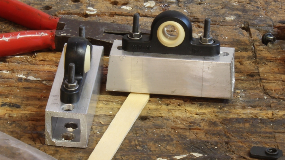 This turned out to be a mistake. The bearings worked fine - great, in fact, since they let me insert the leadscrew at weird angles which made assembly/disassembly much easier - but the lead screw has a distinct 'wiggle' in it when it turns.
I suspect this is due to a combination of the inexpensive 'Made in China' nature of the shaft coupler and because the diameter tolerance of the threaded rod is larger than expected. The 5mm segment of the shaft coupler is so tight it's almost press-fit (which caused me some trouble when the set screw marred the shaft of the stepper motor and prevented me from removing the shaft coupler), but the 8mm threaded rod will fall out if you let it. Additionally at least one coupler doesn't seem to have the hole bored parallel to the long axis.
I'm not 100% sure how to solve this. One idea is to support both ends of the leadscrew with bearing and then any minor misalignment between the motor and the shaft doesn't matter. That's going to require some creative mounting solutions.
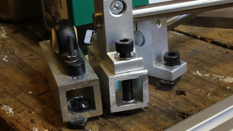
I may bite the bullet and use a couple of timing pulleys to drive the threaded shaft but I haven't made up my mind yet. That's the general idea at least. There are details in the implementation that I haven't touched on, like the booster blocks I needed under the leadscrew bearings, for example:
[ 2013-10-12 ]
First off, a big shout out to RobotDigg! I stumbled across them when I was hunting for parts, and my initial reaction was that it was some kind of scam. The prices were amazing low, the broken English didn't inspire confidence, their order system is a bit wonky (the website just takes the order, they contact you later to arrange payment), and I couldn't find anybody who had successfully ordered from them.
After doing some googling of the owners name (apparently the guy who runs the site owns the factory in China where the parts are made?) and poking around the site a bit I decided that if this was a scam, it was a very well built one. I took a chance and ordered about $40 of parts. A few weeks later, this showed up:
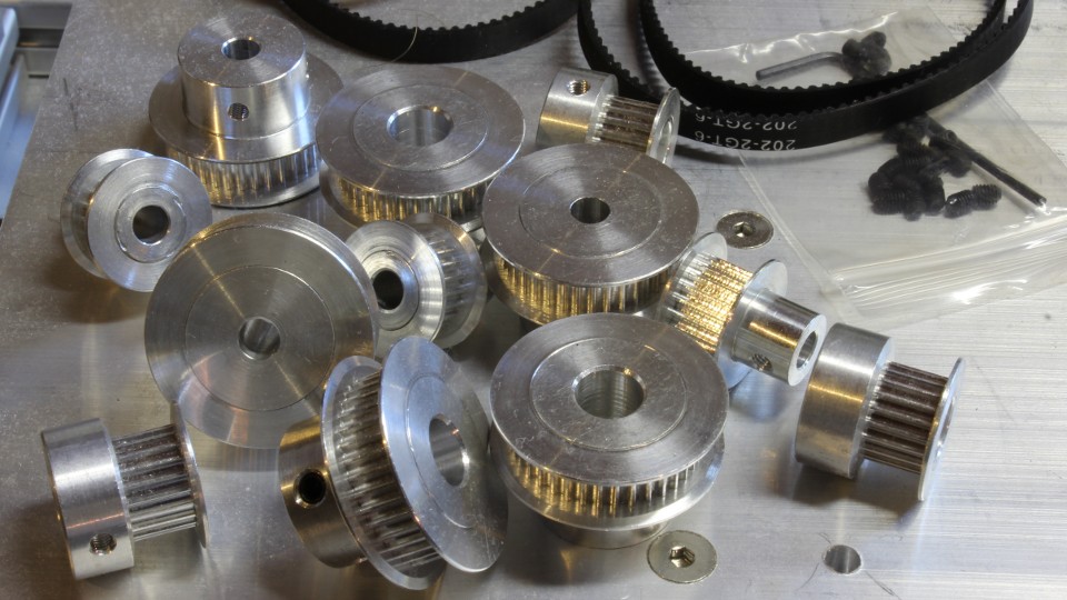
I got three of each type of GT2 pulley offered for 8mm and 5mm shafts. Decent quality too; some extra flashing but everything seems coaxial and the set screws fit well. The only issue I've had so far is the 5mm bore parts are essentially press fit, which resulted in me spending an hour doing this:
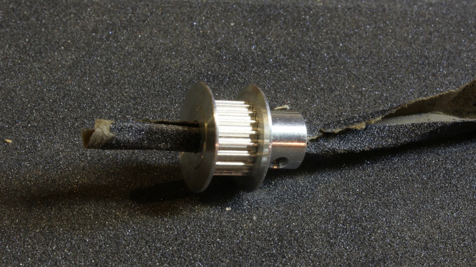
Oh well. I'll gladly spend an hour sanding if it nets me parts at 1/5 the usual cost.
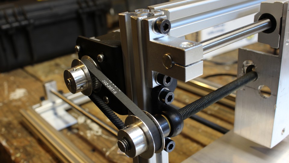
(And to be fair, the shafts on my stepper motors may not be the epitome of exactness either.) RobotDigg doesn't sell just pulleys either; they have a sizable range of CNC/3D printer parts, including linear bearings that appear to be identical to the ones carried by Adafruit, but at a fraction of the cost. No pillowblocks though. The idea was that the pulley/timing belt drive would let me move the motors to more convenient places (namely, inside the footprint of the table), reduce the vibrations transmitted to the frame when running, and support both ends of the leadscrew with bearings (which would negate the issues with the flex shaft couplers). As a bonus I could also tinker with the pulley size ratios to change the precision/speed of the drive. Sadly, even with the largest pulleys and smallest belt, the leadscrew is still off-center. Still, it's probably close enough for my purposes:
(Looks almost professional, doesn't it?) Now I need to wire it up and see how it drives. I may also need to hit up McMaster again, this time for another bearing and some 8mm shaft clamps.
[ 2013-10-13 ]
For those hunting for pulleys and belts for 3D printer and CNC rigs, the RepRap wiki has a couple of nice pages documenting suppliers: Belts and Pulleys, GT2 Timing Belt. I wish I had found these back when I was casting about for parts.
[ 2013-10-16 ]
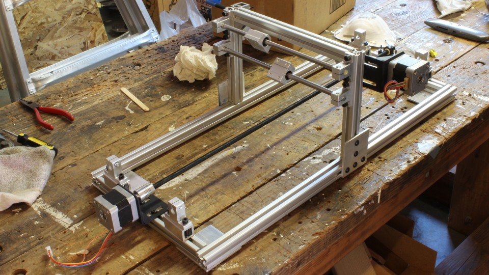
Progress!
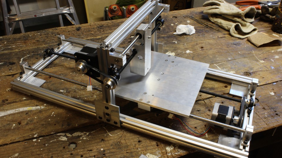
The gantry/Y-axis in this photo is pretty much what I was going for.
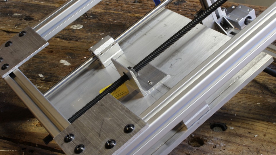
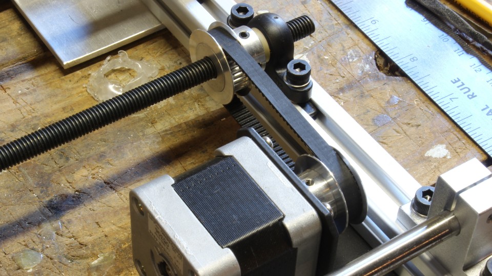
Detail shot of the Y-axis pulley/motor setup.
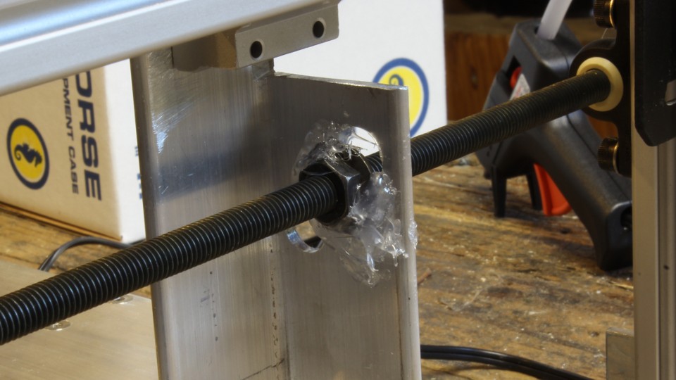
And here is what my hot-glue-and-flange-nut idea looks like when implemented.
I recommend cleaning the aluminum surface and the flange nut with rubbing alcohol before gluing, otherwise everything will peel peel right off.