
1320 Lumen Bike Light
Last Update: January 08, 2015
[September 27, 2014]
One of the hallmark traits of a good hacker (not that I claim to be either) is being a good scrounger. Being able to wrestle usefulness out of stuff that others had thrown or given away using nothing but duct tape and cable ties is a valuable survival instinct and a great way to waste a Saturday afternoon.
In my case I had recently rebuilt my mountain bike, and had thought about hitting some of the local trails at night. I needed a front light for my bike, however, and when doing ~20mph down a rocky hill in the dark one of those el-cheapo store-brand candle-holders isn't going to cut it. I didn't feel like dropping a giant wad of cash on a shiny new 'high-end' bike light either. Fortunately for me, I had my junk box.
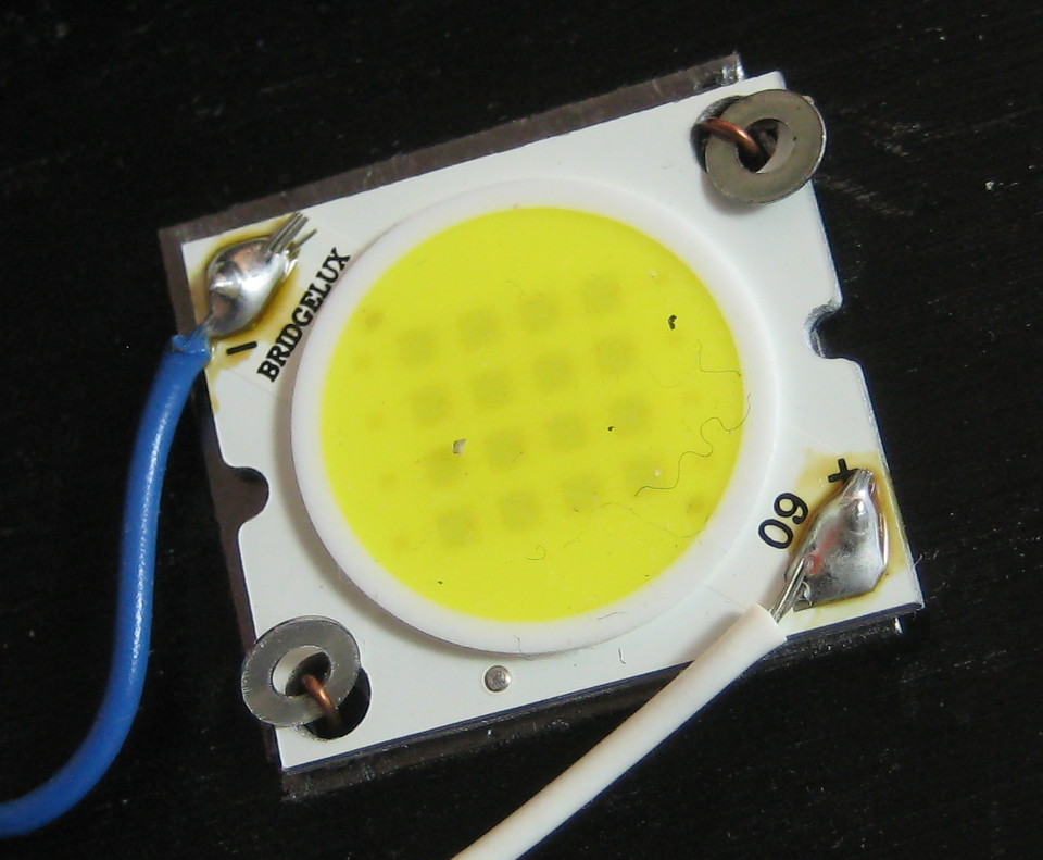
A while back I had wired up LED lights in my workshop and I had a constant-current driver and an LED left over:
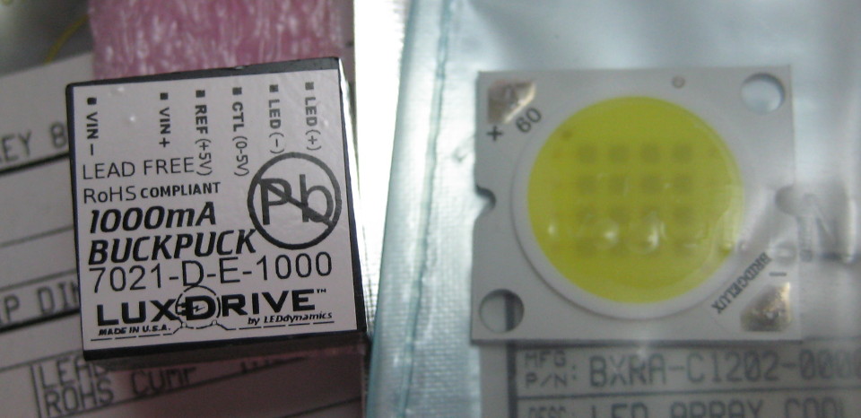
That's a Bridgelux BXRA-C1202-00000 (a 1320 lumen LED array rated for 1 amp at 12.8 volts) and a LEDdynamics LUXdrive BuckPlus 7021-D-E-1000 (1 amp output constant current driver).
I needed to work up some kind of mounting rig, but that should be fairly straightforward. Powering this LED was a bigger issue. I'm not sending this into space nor the bottom of the ocean, but I still have dust, water, vibration, and shock to consider. On top of that I want to keep this battery pack as light as possible and somehow fandangle a convenient and secure mounting system to my bike. And - of course - I want it to be as cheap as possible. Remember what I said about scrounging?
Hard to get cheaper than free.
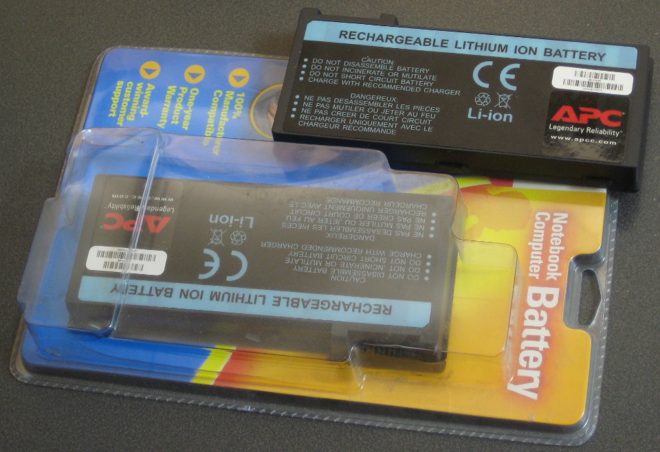
These are APC LBCHP4R Lithium Ion laptop battery packs, generic replacement units that fit Hewlett-Packard Omnibook XE3, Pavillion 5000, N5100, N5200, N5300, N5400, XH1, XH2, XH3, and XH4 laptops. I got them for free from the 'throw away' pile at a local school (the science department was having a post-school-year clean-out and was tossing all sorts of wonderful junk). They're rated at 11.1 V and 5.4 AHr - although I suspect that capacity rating is a bit on the wishful thinking side (always is). Based on the voltage I made the guess that it consisted of three sets of parallel cells in series. I had hoped to use the existing charge and balance circuitry but the battery voltage was too low to be useful - assuming a voltage of 4.2 V at full charge, and 2.5 V at depleted charge, the output voltage ranged from 12.6 to 7.5 volts - below the minimum voltage of the LED in question. I also didn't know how to interface to the completely undocumented connector either.
At that point it made sense to crack the case open and take a look-see, to investigate if I could cobble together cell sets into something more useful. The case popped open easily enough. It's a tongue-and-grove setup with either some kind of adhesive or ultrasonic welding. Either way, it's brittle. Putting sharp pressure right on the seam makes a delightful cracking noise, so I just worked my way around the perimeter of the case until it started separating and then carefully pried it off with a knife, screwdriver, and some elbow grease.

Hot diggity! Panasonic/Matsushita cells! Not some generic/no-name brand of questionable build quality. These are 18650 sized cells rated at 1800 mAHr, probably cost at least $4 each so we're looking at $40 worth of Lithium Ion cells, at minimum. Nice! Also, they're orange. Orange color is best color. Somewhat surprisingly the larger half of the case (the half with the labels) came off first. Note that the case has vents molded in so the exterior labels actually stick to the cells. In the future, it would probably be easier to peel the labels off first and then try to get the case open.
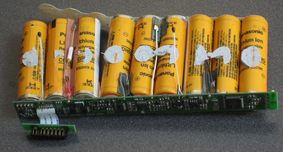
The cells themselves are glued to the bottom half of the case with some kind of rubbery cement. Getting them separated from the plastic takes some time, patience, and a plastic prying tool of some description (metal tends to rip up the plastic coating on the cells themselves). Once they're free you can get a look at the wiring. The white cylinder thing on the left is either a thermal cutoff or a polyfuse (cuts off the current if the current passing through it exceeds a given amount). The little black blobs are temperature sensors of some kind, probably thermistors. The gray and white wires are the usual balance and charge connections.

And, hey look, I was right: three sets of parallel cells in series. Slapping another set of cells on the end of the chain gives me a voltage range of 10 to 16.8 volts, which works out great because the LED array will cut off at 12.7ish (~3.2 volts per cell). This is a conservative cut-off voltage but the only way to get closer to the cells minimum voltage is to involve voltage sense circuity of some kind. I probably don't have the parts and honestly I can't really be bothered. It's Saturday! I'm trying to
The copyright on the packaging lists the year as 2002, strongly suggesting that these batteries had been sitting on the shelf for over a decade. Normally I wouldn't hold out much hope but these packs don't appear to have ever been used and they're name-brand cells - maybe I can wake them up with some TLC . Pack condition isn't critical for this application; I'm not particularly worried if I only get a fraction of the battery power out of it. New problem: I don't have the appropriate charger for a Lithium Ion pack this size - but I do have a charger for a pack half this size, a Powerizer 3P10-L0508. Solution? Split the pack in half:
 This is the part where I tell you that it is dangerous and probably stupid to assemble a pack like this. This battery requires MANUAL voltage balancing. When assembling a battery pack yourself, use of dedicated under/over voltage protection and balancing circuitry is strongly recommended.
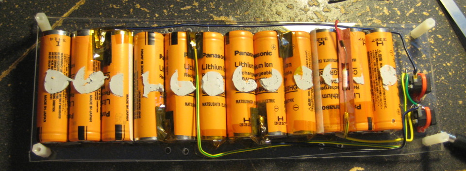
INFORMATION PROVIDED HERE IS SUPPLIED FOR ENTERTAINMENT PURPOSES ONLY; NO WARRANTY OR GUARANTEE IS IMPLIED OR SUPPLIED. USE AT YOUR OWN RISK. Note the two barrel jack connectors on the right, one for each half of the pack. The yellow-green wires are positive connections and the dark blue wires are the negative connections. (Apologies for the non-nonsensical color coding; I was using wire I had scavenged from a friends 1999 Mazda Miata.
Sure, they might not be in the best of conditions but they're usually more than sufficient for your average hobbyist needs. Back to the photo. The barrel jacks are just for charging - having these sockets built in eliminates several potential failure vectors when hooking up the charger and lets me test the condition of the pack without having to pull the whole thing out of the case.
Notice the green wire jumper on the far right, between the two barrel jacks. This wire connects both halves in series, but in this photo I had yet to attach the output connector for the pack. Note that I saved the thermal cutoff/polyfuse from the original battery; this is the positive output of the pack. The negative wire will connect to the upper left end of the pack.
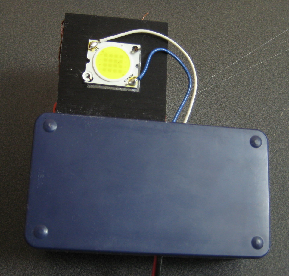
I used some 16 AWG wire salvaged from a busted ATX power supply and attached a Hextronik XT60 connector.
I sandwiched the pack between some foam and scrap acrylic plates, and used nylon stand-offs and cable ties to hold everything together. The nominal pack capacity is listed as 5.4 AHr, and my charger outputs a pitiful 0.5 amps. Thus, I should expect each half to take between ten and eleven hours to charge. So far, this is looking accurate.
When the pack is charged up I'll assemble the LED and driver, and test out the condition of the cells. Further updates as events warrant.
[January 08, 2015]
Photos!
Sadly I didn't have the parts and tools at hand for a proper job, but keeping with the 'quick Saturday project' aesthetic I feel I came up with a novel solution:
 Yes, those are washers pulled tight against the LED via copper wire which is unceremoniously wrapped around some of the fins on the heatsink:
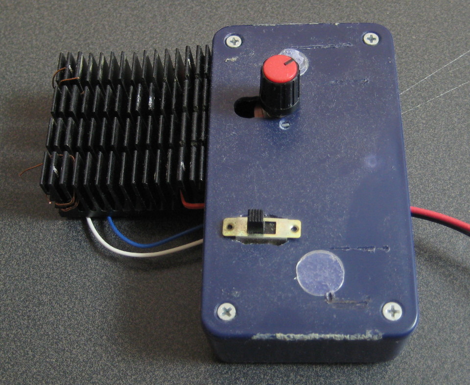 You may contact me via the email on the front page of this website, NASA. I have plenty of other novel mechanical mounting techniques I'd be willing to share for a reasonable fee.
Joking aside, it is not ideal and given the opportunity I would have used a 3 mm tap to put some threads in there - but alas McMaster doesn't have a same-day delivery option. Thing is though, it is 'good enough' for my purposes. The heatsink is from a Intel 486 system or similar, it's held to the box with a couple of cable-ties.
You may contact me via the email on the front page of this website, NASA. I have plenty of other novel mechanical mounting techniques I'd be willing to share for a reasonable fee.
Joking aside, it is not ideal and given the opportunity I would have used a 3 mm tap to put some threads in there - but alas McMaster doesn't have a same-day delivery option. Thing is though, it is 'good enough' for my purposes. The heatsink is from a Intel 486 system or similar, it's held to the box with a couple of cable-ties.That switch is a red herring - I'm reusing a box from a previous project and the switch doing a good job plugging a hole in the box - but that potentiometer is legit and is connected to the dimming wires on the constant current controller. Sadly that controller dimming function is finicky; the pot operates more like a power switch than anything. Here is the other side:
 My mother has offered to sew up a bag that'll velcro the battery pack to the bike frame, so keep an eye out for that at some point. Hopefully the next update will have photos of the system in operation.