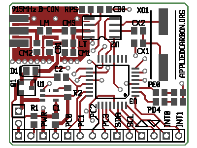
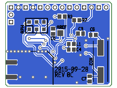
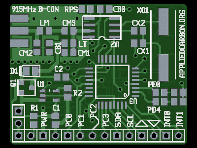
915 MHz ISM Band Beacon ('915MHZ B-CON')
Last Update: Sep 28, 2015
- Features At a Glance
- Photos
- Schematic Diagram
- Example Firmware
- Receiver Reference Design
- Design Notes
Features At a Glance
- ATMega 48PB/88PB/168PB/328PB Microcontroller
- 32.768 kHz clocked counter for time keeping (optional)
- Band-gap reference for battery voltage monitoring
- Internal temperature sensor
- Melexis TH72031 (ASK) or TH72032 (FSK) 915 MHz ISM Band Radio
- Microchip MCP73831 Lithium Ion cell charger
- 1.45" x 1.15" Board
- Sub-$10 Bill of Materials
Photos and Images


Schematic Diagram
Schematic as a PNG image.Also available in Expanded PostScript Format.
Example Firmware
Coming soon....Receiver Reference Design
Coming soon....Design Notes
This project started when I set out to make 'throwable' (i.e. cheap enough to be used on projects with a very low chance of recovery) sensor board with a radio link. This is the second generation of the solution I engineered, and I think it works quite well. It's designed to be the core of a larger project: it provides a radio link that operates in the 915 MHz ISM band, an Atmel ATMega48PA microcontroller, and Lithium Ion cell charger. From looking at other sensor networks and IoT projects and development kits, I think these items are the bare minimum needed to make a useful platform. I didn't quite make the sub-$10 goal for the whole sensor/telemetry board that this project was supposed to be, but with this board as the core a sub-$20 project should be easily possible. RadioI've always been frustrated with the state of radio communications in the hobby electronics arena. All the devices I've seen tend toward expensive and complex, likely due to a plethora of built in features that most people have no need for (I'm looking at you, XBee). The recent availability of extremely low cost Wifi dongles alleviates this somewhat, but Wifi is only good for short range communications and still requires a significant amount of infrastructure. I wanted something that was low power, long range, connectionless, had low computational overhead, was hand-solderable, and cost a dollar at most.
The Melexis TH72031/TH72032 parts fit the bill. They're not much more than an oscillator/PLL and a power amplifier - exceedingly simple and thus exceedingly cheap. The former part does Amplitude Shift Keying/On Off Keying (think Morse code) and the latter does Frequency Shift Keying (think binary). As a bonus they share the same footprint, which lets the user choose the transmit method that best fits their purposes. The board has a jumper that lets the user connect the radio chip data input pin to the output pin of the microcontrollers UART. No need to bit-bang messages here!
These chips pack a significant amount of power into a very small package: I've personally tested it out to several hundred feet with a house and trees in the way with little degradation in signal.
There is a trade off with this simplicity however, in that the radio only provides a one-way link and there isn't (yet) a true turn-key solution for the receivers end. A $10 RTL-SDR dongle and a cheap 915 MHz ISM band antenna from eBay is all you need to pick up the signal, but a little mathematical magic is needed to convert the output into a text string on a computer (see the Receiver Reference Design section for more details). Processing
The ATMega48PA is essentially the same microcontroller found in the well known and widely used Arduino platform, just with a smaller flash memory. The PA variant in particular has the option to use a Time/Counter module with a 32.768 kHz crystal to implement a "Real Time Counter" - a crude version of a Real Time Clock. I had planned to put an RTC chip on the board for scheduling purposes (e.g a weather beacon that wakes up once a day to poll sensors and send data) but this "RTC" provides essentially the same functionality without the cost of the extra parts.
Additionally, it has an internal band-gap reference which can be used to measure battery voltage, an internal temperature sensor (admittidly a bit inaccurate), and a bunch of useful hardware interfaces (SPI, I2C, serial, external interupts, ADCs, GPIO). Power
The name of the game here is 'scales of economy'. The board is designed to have roughly the same footprint as a cell phone battery; my intention was to simply tape the battery to the bottom of the board. Cell phones are ubiquitous in the world and every single one of them needs a lithium ion battery, so it makes a lot of sense to try to use these cells. They're easy to obtain and most of us have a one or two spare cells laying from from old phones anyway.
The system runs directly off the cell; the board doesn't come with a boost-buck converter. This was a deliberate decision: most DC-DC converter devices don't come in packages that are easy to hand solder, a converter circuit would involve more parts and thus increase cost, and it would introduce EMI to the board which could interfere with the radio. I was also worried about power use, particularly when the system was supposed to be asleep, although the increased operational voltage may have made up for that. All the devices included on the board operate over the entire voltage range of the average Li+ cell. If a user wishes to add a step-up/step-down DC-DC converter, I recommend the selection of inexpensive, breadboard-ready converters available at Pololu.