
Thirty-two digit, 7+1 Segment LED Display Panel
Last Update: April 08, 2015
- Features At a Glance
- Disclaimer
- Photos
- Connector Diagrams
- Function Select Jumpers
- Serial Commands
- Schematic Diagram
- Firmware
Features At a Glance
- Thirty-two (32) digits of 7+1 segment LED displays
- Holtek HT1632C LED display driver (Each LED segment is individually controllable. On-board RAM, no display driver needed.)
- Atmel ATTiny 2313A microcontroller (plus 11.0592MHz crystal)
- Serial/UART communication interface
- Display memory can be both written to and read from by the user
- 8.700" x 1.575" two layer printed circuit board (FR-4, 1 oz copper, black matte solder mask, HASL pad finish)
- 0.130" mounting holes on 8.350" x 1.225" centers
Disclaimer
This product is currently intended for hobbyist purposes ONLY. No guarantee is made for suitability for any purpose. All efforts have been made to ensure accuracy of information and to deliver a quality product, however the product and information shown here are provided AS IS.In particular, this system is NOT FOR USE IN SAFETY CRITICAL APPLICATIONS, including but not limited to life support, aerospace, and automotive systems.
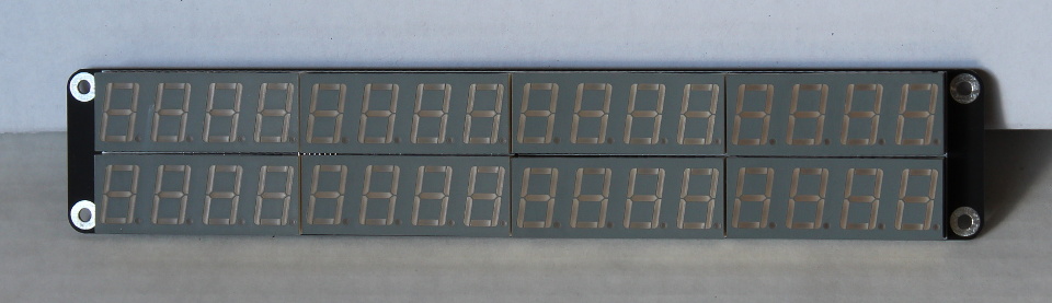
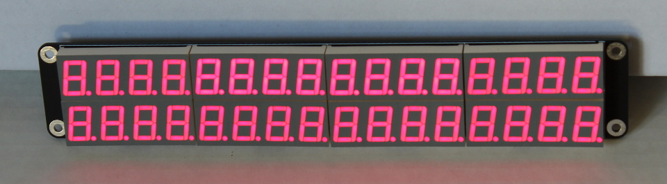
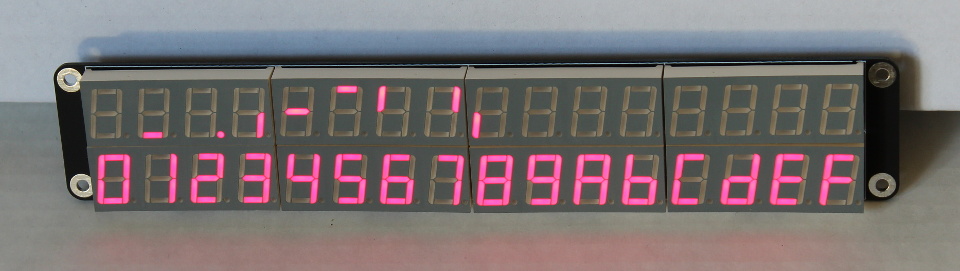
Photos
The following photos are from the production (Rev 1) version of the display: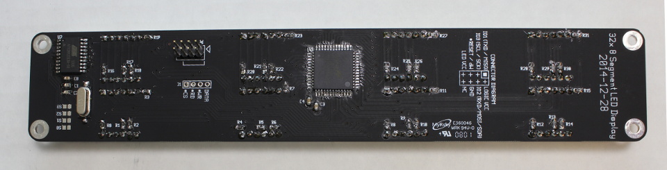
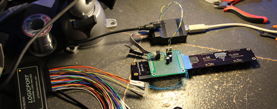
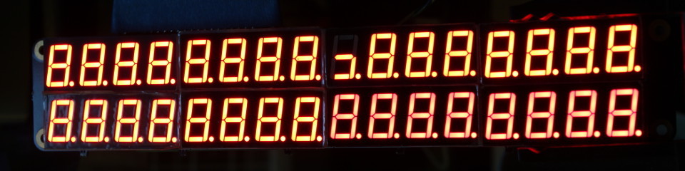
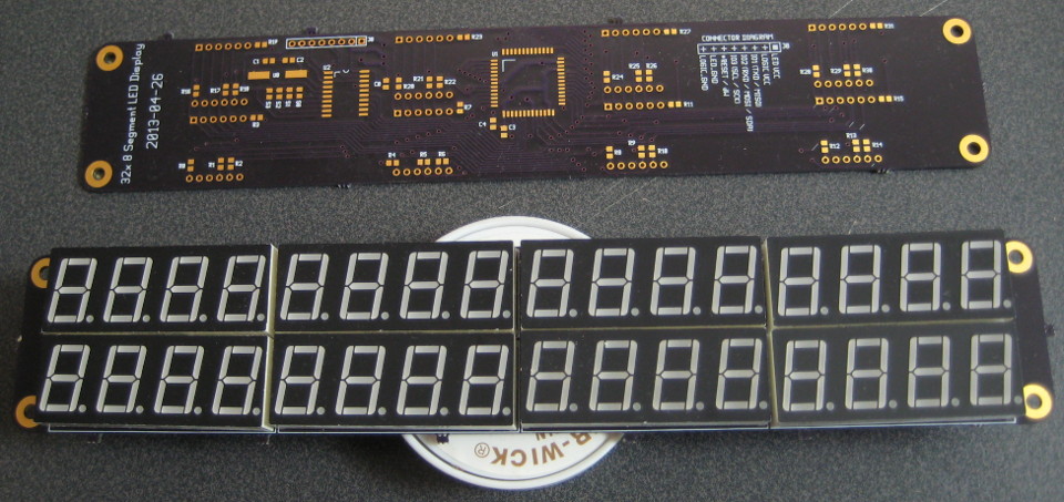
 The following photos are from the development (Rev 0) version of the display:
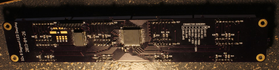
Connector Diagrams
The primary connection for the display is a two pin by four pin, 0.1" pitch connector on the back on the board:
This connector multiplexes UART, SPI, and I2C communication buses onto one connector. Only one bus may be used at a time. The ATTiny2313 microcontroller may be programmed over the SPI bus as normal; the top six pins of the connector match the standard AVR programming header layout. The LED VCC pin does not need to be powered or connected in order to program the microcontroller. The display is designed to be operated from a regulated five volt DC power supply. Note that there is no on-board power regulation. The Logic VCC and LED VCC pins may be connected to the same power rail.
Function Select Jumpers
The communication bus used by the display is selected by jumpers S0 through S3, as shown in the table below:| S3 | S2 | S1 | S0 | Function |
|---|---|---|---|---|
| - | - | - | - | Serial Connection, 2,400 baud |
| - | B | - | - | Serial Connection, 9,600 baud |
| B | - | - | - | Serial Connection, 57,600 baud |
| B | B | - | - | Serial Connection, 115,200 baud |
- = pads clear/separated
B = pads bridged All other configurations are reserved for future use. Jumper states are latched on power-up. Changing jumper states during operation has no effect on the system.
Serial Commands
The serial connection option uses an AT-command structure similar to that which is found in many serial modems:| Command | Returns | Purpose |
|---|---|---|
| AT | OK | ATtention Verify functioning of device |
| V | [Text String] | Version A string identifying the manufacturer, product, and build number (version) of the firmware |
| DC | OK | Display, Clear Clears display. (All segments off.) |
| DBS[address][pattern] | OK | Display, Binary, Set Sets status of the segments of a given digit on the display. Address is three digits in ASCII (zero padded, 0 to 255) that indicate a digit. Pattern is three digits in ASCII (zero padded, 0 to 255) that encode a binary bit pattern. See table below for bit-to-segment mapping details. |
| DBG[address] | [ASCII number] | Display, Binary, Get Gets the status of the segments of a given digit on the display. Same data format as above. |
| DNS[address][value] | OK | Display, Number, Set Sets the status a given digit so that the provided value is shown. Address is three digits in ASCII (zero padded, 0 to 255) that indicate a digit on the display. Value is one of the following ASCII characters: 0, 1, 2, 3, 4, 5, 6, 7, 8, 9, A, B, C, D, E, F |
| DON | OK | Display, ON Turns on display |
| DOF | OK | Display, OFf Turns off display (default state) |
| BON | OK | Blink, On Enables blinking of display. Very annoying. |
| BOF | OK | Blink, OFf Disables blinking of display. (default state) |
| PS[value] | OK | PWM brightness, Set Set the PWM brightness to the specified value. Value must be between 0 and 15, zero padded. |
Schematic Diagram
Firmware
The source code for the ATTiny2313A microcontroller available both in C source code form, and in hex format. AVR-GCC was used to compile the firmware, and the hex file is suitable for use with avrdude utility and the programmer of your choice. The ATTiny2313A microcontroller 'low' fuse byte was set to0xFF with the following command:
avrdude -c usbtiny -p attiny2313 -U lfuse:w:0xFF:m
The firmware is released under a modified beer-ware license. See source file header for details.